Magnetostrictor actuator

A magnetostrictive and actuator technology, applied in the direction of piezoelectric effect/electrostrictive or magnetostrictive motors, generators/motors, electrical components, etc., can solve the complex structure of the actuator and the increase in overall size and other issues, to achieve the effect of good linear drive performance

Active Publication Date: 2010-01-13
杨锦堂 +1
View PDF1 Cites 20 Cited by
  • Summary
  • Abstract
  • Description
  • Claims
  • Application Information

AI Technical Summary

Problems solved by technology

Although this solution has a good cooling effect, the structure of the entire actuator is complicated, the overall size is increased, and it also requires additional pumping systems and other defects.

Method used


Image

  • Magnetostrictor actuator
  • Magnetostrictor actuator
  • Magnetostrictor actuator

Examples


Embodiment 1

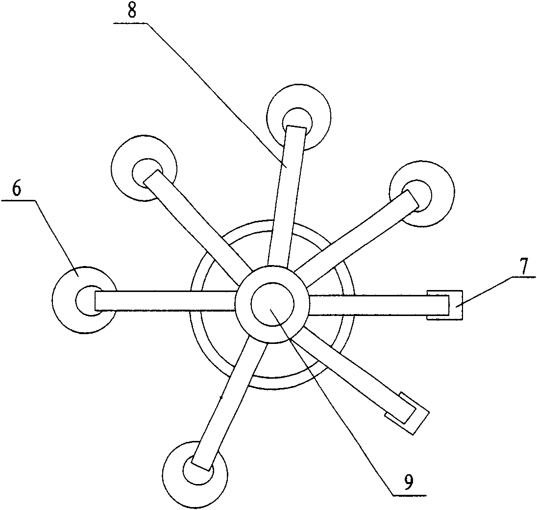
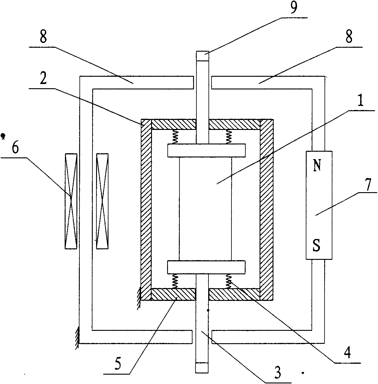
[0027] Such as figure 1 , 2 , 3, the mechanism of the present invention includes a rigid non-magnetic support 2 and a magnetostrictive body 1 arranged in the rigid non-magnetic support 2, and the opposite sides of the rigid non-magnetic support 2 are provided with through openings. A rigid magnetically conductive rod 3 that can move freely relative to the through opening is provided, and the rigid magnetically conductive rod 3 is fixedly connected to the magnetostrictive body 1; One side is open, and the other sides are closed; the periphery of the rigid magnetic conductive support 8 is wound with an electromagnetic coil 6; the magnetostrictive body 1, the rigid magnetic conductive rod 3 and the rigid magnetic conductive support 8 form an electromagnetic flux circuit 10, Set five. The rigid magnetically conductive rod 3 can move freely relative to the opening side of the rigid magnetically permeable support; the rigid non-magnetically permeable support 2 and the rigid magnet...

Embodiment 2

[0035] Such as Figure 4 As shown, the mechanism of the present invention includes a rigid non-magnetic support 2 and a magnetostrictive body 1 arranged in the rigid non-magnetic support 2. One side of the rigid non-magnetic support 2 is provided with a through opening, and the through opening is arranged relative to the through opening. A rigid magnetically conductive rod 3 that can move freely, and the rigid magnetically conductive rod 3 is fixedly connected to the magnetostrictive body 1; a rigid magnetically conductive support 8 is provided on the outside of the rigid non-magnetically conductive support 2, and one side of the rigid magnetically conductive support 8 is open , the remaining sides are closed; the rigid non-magnetically conductive support 2 is provided with an opening on the side opposite to the through opening, and the rigid magnetically conductive support 8 is directly connected to the magnetostrictive body 1 after penetrating through the opening. An electro...

Embodiment 3

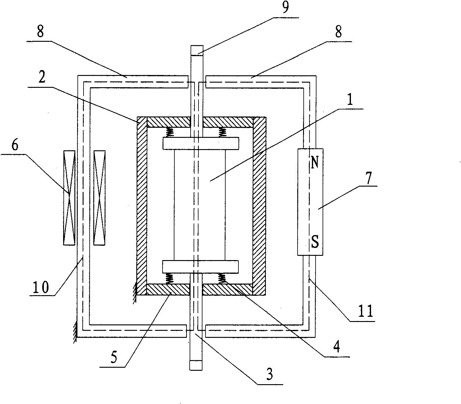
[0038] Such as Figure 5 As shown, the mechanism of the present invention includes a rigid non-magnetic support 2 and a magnetostrictive body 1 arranged in the rigid non-magnetic support 2. The opposite sides of the rigid non-magnetic support 2 are provided with through openings. The rigid magnetically conductive rod 3 that can move freely at the through-hole, the rigid magnetically conductive rod 3 is fixedly connected with the magnetostrictive body 1; One side is open, and the other sides are closed; the periphery of the rigid magnetically conductive support 8 is wound with an electromagnetic coil 6; The magnetostrictive body 1 is excited. The rigid magnetically conductive rod 3 can move freely relative to the opening side of the rigid magnetically permeable support; the rigid non-magnetically permeable support 2 and the rigid magnetically permeable support 8 are both fixedly arranged.

[0039] A spring 4 is arranged on both sides of the rigid magnetic rod 3 in contact wit...


PUM


Abstract

The invention relates to an electrostrictive or magnetostrictive motor or a generator which can generate linear movement. The magnetostrictor actuator comprises a rigid non-magnetic support and a magnetostrictor which is arranged in the rigid non-magnetic support; one side of the rigid non-magnetic support is provided with a through opening, or two opposite sides of the rigid non-magnetic support are provided with through openings; a rigid magnetic rod which can freely move relative to the through opening is arranged in the through opening and is fixedly connected with the magnetostrictor; a rigid magnetic support is arranged outside the rigid non-magnetic support; one lateral side of the rigid magnetic support is open, and the other lateral sides are closed; an electromagnetic coil is winded round the periphery of the rigid magnetic support; the magnetostrictor, the rigid magnetic rod and the rigid magnetic support form an electric magnetic flux circuit; the rigid magnetic rod can freely move relative to the open side of the rigid magnetic support; and the rigid non-magnetic support and the rigid magnetic support are fixedly arranged. The mechanism of the invention can be used for researching and producing the instrument and the equipment requiring large-displacement, large-load and high-precision driving function.

Description

technical field [0001] The present invention relates to a motor or generator utilizing electrostriction or magnetostriction for producing linear motion, and more particularly to an actuator. Background technique [0002] In recent years, the field of electric and magnetostrictive materials has developed rapidly, and new magnetostrictive smart materials such as giant magnetostrictive materials and magnetostrictive shape memory alloys have been produced, which can be used in the development of precision actuators. These materials have It has the advantages of high energy density, high output power, large expansion and contraction deformation, and precise control. However, the actuation devices developed based on such stretchable materials often require high current excitation that can generate strong electromagnetic fields in order to achieve large telescopic displacement and large load actuation capabilities. However, due to the limitation of the design structure of the brak...

Claims


Application Information

Patent Timeline
Patent Type & Authority Applications(China)
IPC IPC(8): H02N2/00H02N2/02
Inventor 杨锦堂李健
Owner 杨锦堂
Why Eureka
Try Eureka