Magnetostrictor actuator
A magnetostrictive and actuator technology, applied in piezoelectric effect/electrostrictive or magnetostrictive motors, generators/motors, electrical components, etc. and other problems, to achieve the effect of good linear drive performance
- Summary
- Abstract
- Description
- Claims
- Application Information
AI Technical Summary
Problems solved by technology
Method used
Image
Examples
Embodiment 1
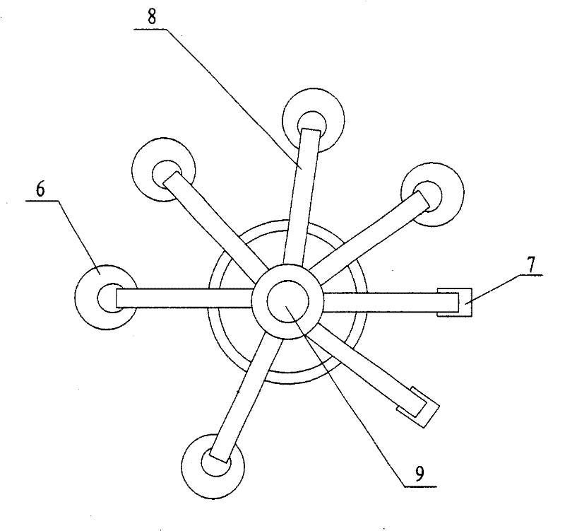
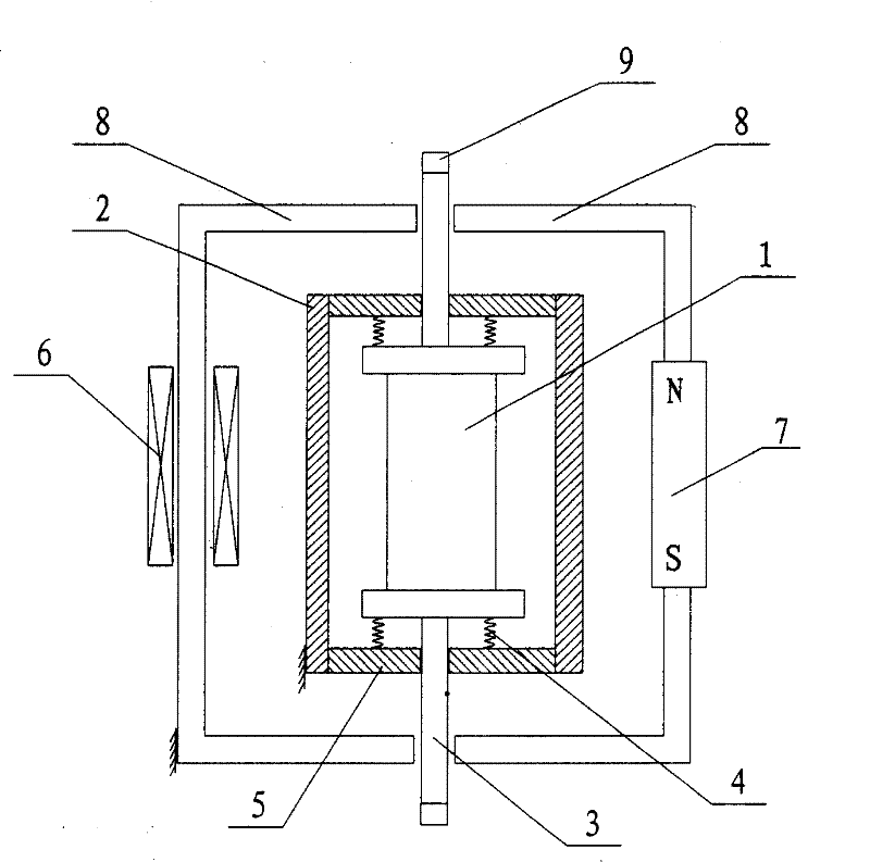
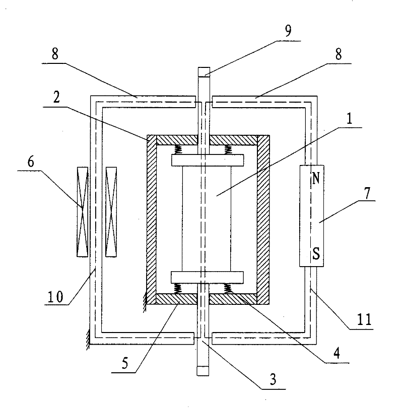
[0028] Such as figure 1 , 2 , 3, the mechanism of the present invention includes a rigid non-magnetic support 2 and a magnetostrictive body 1 arranged in the rigid non-magnetic support 2, and the opposite sides of the rigid non-magnetic support 2 are provided with through openings. A rigid magnetically conductive rod 3 that can move freely relative to the through opening is provided, and the rigid magnetically conductive rod 3 is fixedly connected to the magnetostrictive body 1; One side is open, and the other sides are closed; the periphery of the rigid magnetic conductive support 8 is wound with an electromagnetic coil 6; the magnetostrictive body 1, the rigid magnetic conductive rod 3 and the rigid magnetic conductive support 8 form an electromagnetic flux circuit 10, Set five. The rigid magnetically conductive rod 3 can move freely relative to the opening side of the rigid magnetically permeable support; the rigid non-magnetically permeable support 2 and the rigid magnet...
Embodiment 2
[0036] Such as Figure 4 As shown, the mechanism of the present invention includes a rigid non-magnetic support 2 and a magnetostrictive body 1 arranged in the rigid non-magnetic support 2. One side of the rigid non-magnetic support 2 is provided with a through opening, and the through opening is arranged relative to the through opening. A rigid magnetically conductive rod 3 that can move freely, and the rigid magnetically conductive rod 3 is fixedly connected to the magnetostrictive body 1; a rigid magnetically conductive support 8 is provided on the outside of the rigid non-magnetically conductive support 2, and one side of the rigid magnetically conductive support 8 is open , the remaining sides are closed; the rigid non-magnetically conductive support 2 is provided with an opening on the side opposite to the through opening, and the rigid magnetically conductive support 8 is directly connected to the magnetostrictive body 1 after penetrating through the opening. An electro...
Embodiment 3
[0039] Such as Figure 5 As shown, the mechanism of the present invention includes a rigid non-magnetic support 2 and a magnetostrictive body 1 arranged in the rigid non-magnetic support 2. The opposite sides of the rigid non-magnetic support 2 are provided with through openings. The rigid magnetically conductive rod 3 that can move freely at the through-hole, the rigid magnetically conductive rod 3 is fixedly connected with the magnetostrictive body 1; One side is open, and the other sides are closed; the periphery of the rigid magnetically conductive support 8 is wound with an electromagnetic coil 6; The magnetostrictive body 1 is excited. The rigid magnetically conductive rod 3 can move freely relative to the opening side of the rigid magnetically permeable support; the rigid non-magnetically permeable support 2 and the rigid magnetically permeable support 8 are both fixedly arranged.
[0040] A spring 4 is arranged on both sides of the rigid magnetic rod 3 in contact wit...
PUM
 Abstract
Description
Claims
Application Information
 - R&D
- Intellectual Property
- Life Sciences
- Materials
- Tech Scout
- Unparalleled Data Quality
- Higher Quality Content
- 60% Fewer Hallucinations
Browse by: Latest US Patents, China's latest patents, Technical Efficacy Thesaurus, Application Domain, Technology Topic, Popular Technical Reports.
© 2025 PatSnap. All rights reserved.Legal|Privacy policy|Modern Slavery Act Transparency Statement|Sitemap|About US| Contact US: help@patsnap.com


