Apparatus and methods for bone surgery

A technique of surgery and operation, applied in the direction of surgery, surgical saw, femoral head, etc., can solve the problem of component wear and so on

Inactive Publication Date: 2010-02-03
INT PATENT OWNERS CAYMAN
View PDF0 Cites 5 Cited by
  • Summary
  • Abstract
  • Description
  • Claims
  • Application Information

AI Technical Summary

Problems solved by technology

Thus, in the long run, misaligned prosthetic components wear out more rapidly, leading to aseptic loosening of these components and the possible need for earlier re-surgery

Method used


Image

  • Apparatus and methods for bone surgery
  • Apparatus and methods for bone surgery
  • Apparatus and methods for bone surgery

Examples


Embodiment Construction

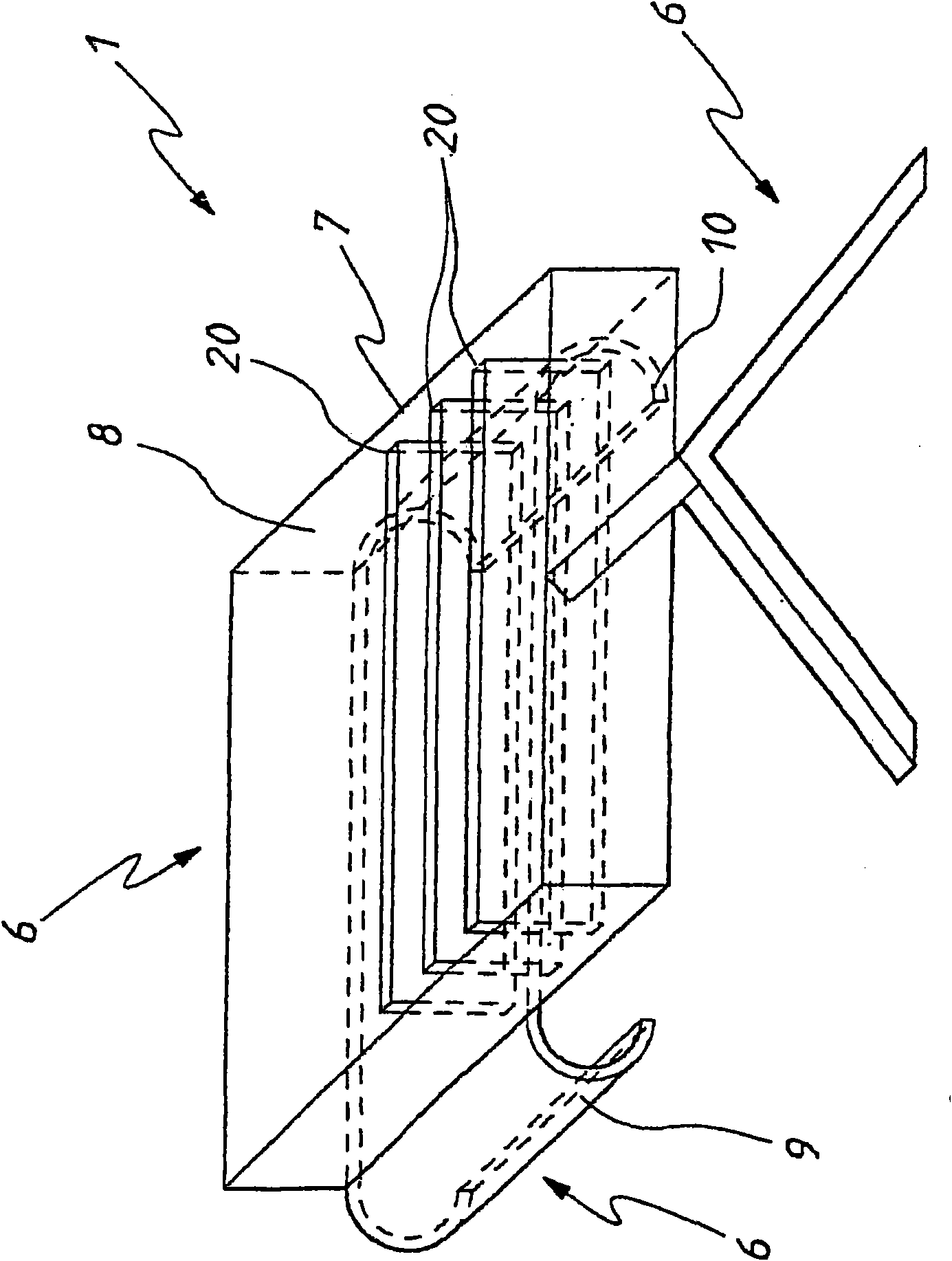
[0058] refer to figure 1 , Surgical Fixture 1 is suitable for applications such as Figure 17 On the femur 2 clearly shown in , the femur 2 includes a femoral head 3 , a femoral neck 4 and a greater trochanter 5 , wherein the femoral neck 4 is usually but not necessarily the cutting position. If the surgeon chooses to use the LINK T.O.P. Cup and C.F.P. Stem in hip replacement surgery, then the femoral head 3 must be amputated (in other words "cut") by a cutting operation along a line transecting the femoral neck. The line is carried out, and its position is about 1.5 cm away from the base of the greater trochanter 5. Of course, other prosthetics, such as the MARGRON THR and SP 2 devices, may require cutting at other locations on the femur 2, such as across the greater trochanter 5. For these applications, a suitable geometry of the clamp 1 is required.

[0059] The jig 1 includes jig positioning means 6 adapted to fit the bone structures 3, 4 and 5 in order to position the ...


PUM


Abstract

The present invention relates to an apparatus and a method for bone surgery. The surgeon grasps the jig by its handle and manipulates the head of the jig through the patient wound and onto the femoralneck. The head of the jig includes jig location means in the form of an elongate rod which acts as a spacer. The spacer has an end which abuts the trochanteric fossa so as to position the slot of thejig at the required position, which is between 5 mm and 25 mm, and most preferably 15 mm, from the trochantic fossa. Additional jig location means are provided by a surface adapted to receive a boneformation. This surface is provided by contours on the base of the head which are adapted to mate with contours of the femur. The slot is oriented generally perpendicularly to the elongate dimension of the rod. The slot functions as a surgical tool guide means which is positioned by the jig at the correct position for osteotomisation of the neck. Advantageously, osteotomisation takes place while the femoral head is still disposed within the acetabulum.

Description

[0001] This application is based on the divisional application of No. 02826140.2 application titled "Apparatus and Method for Orthopedic Surgery" and filed on November 1, 2002. technical field [0002] The present invention relates to surgical devices for use in hip replacement surgery, surgical jigs for use in such surgery. Background technique [0003] Existing hip replacement surgery generally involves first making a large initial incision to expose the hip joint. Next, the surgeon will typically massage the patient's leg to dislocate the hip. This procedure often requires the application of enormous forces to achieve the dislocation. Excessive manipulation and application of great force can cause concurrent damage to the patient, potentially causing post-operative pain and / or prolonging recovery time. Next, the head of the femur is amputated at the neck. A pocket is drilled in the hip to receive a prosthetic acetabular cup (such as a LINK T.O.P acetabular cup) and a p...

Claims


Application Information

Patent Timeline
Patent Type & Authority Applications(China)
IPC IPC(8): A61B17/56A61B17/15A61B17/17A61B17/16A61B17/32A61B17/88A61B17/92A61F2/02A61F2/34A61F2/36A61F2/46
CPCA61B17/1604A61F2/4684A61F2/4657A61F2002/3611A61F2250/0006A61B17/8866A61B17/32A61F2002/4619A61F2002/30538A61B17/92A61F2002/4623A61F2/34A61B17/885A61B17/175A61B17/1746A61B17/15A61F2002/4687A61F2/4603
Inventor 尤金·谢里迈克尔·伊根
Owner INT PATENT OWNERS CAYMAN
Why Eureka
Try Eureka