Mosquito net stand
A mosquito net rack and mosquito net technology, which can be applied to other seating furniture, home appliances, insect nets, etc., can solve the problems of inconvenient use, uncoordinated, troublesome mosquito nets, etc., so as not to affect the appearance, not easy to be damaged, and increase the visual Enjoy the effect
- Summary
- Abstract
- Description
- Claims
- Application Information
AI Technical Summary
Problems solved by technology
Method used
Image
Examples
Embodiment 1
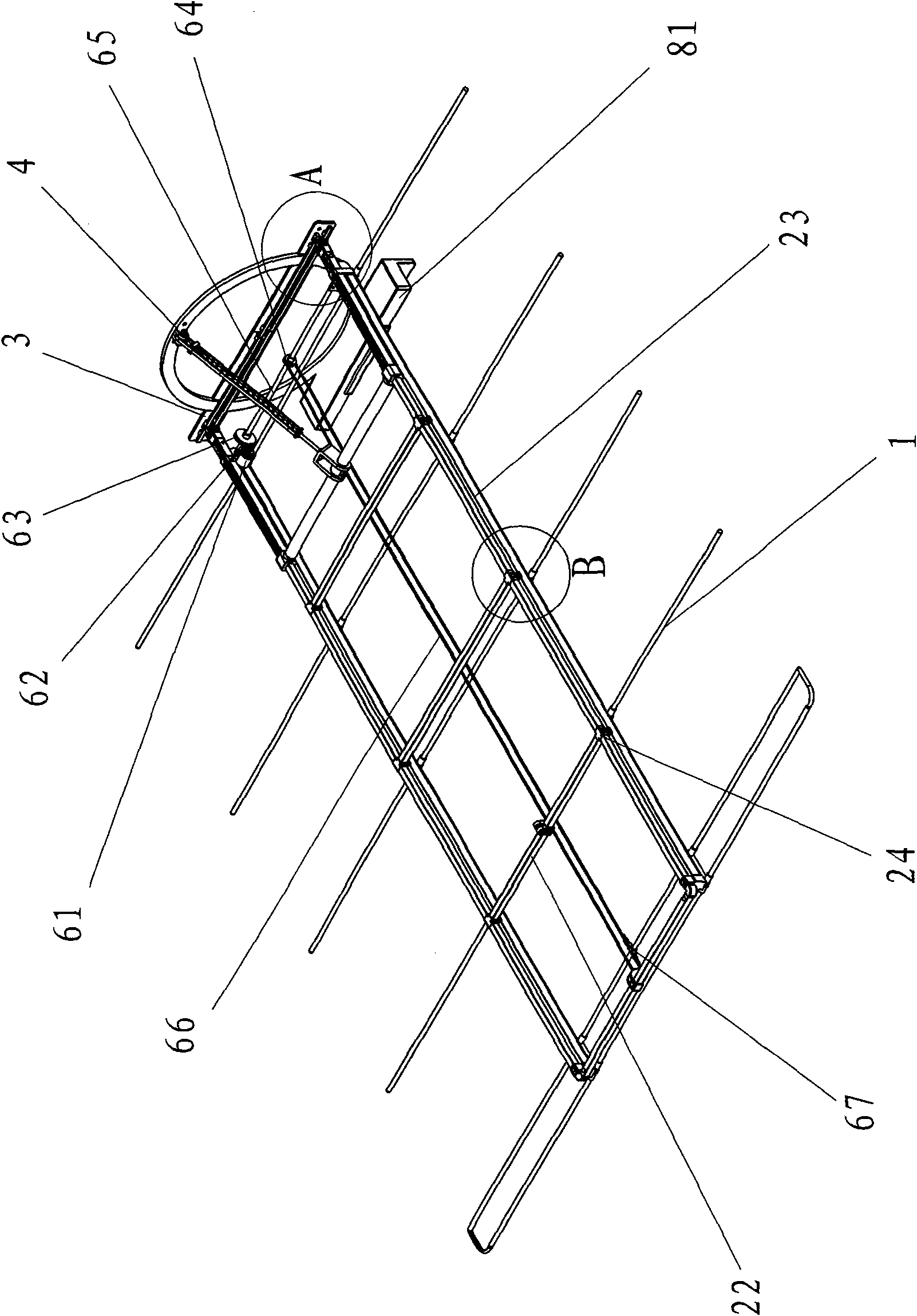
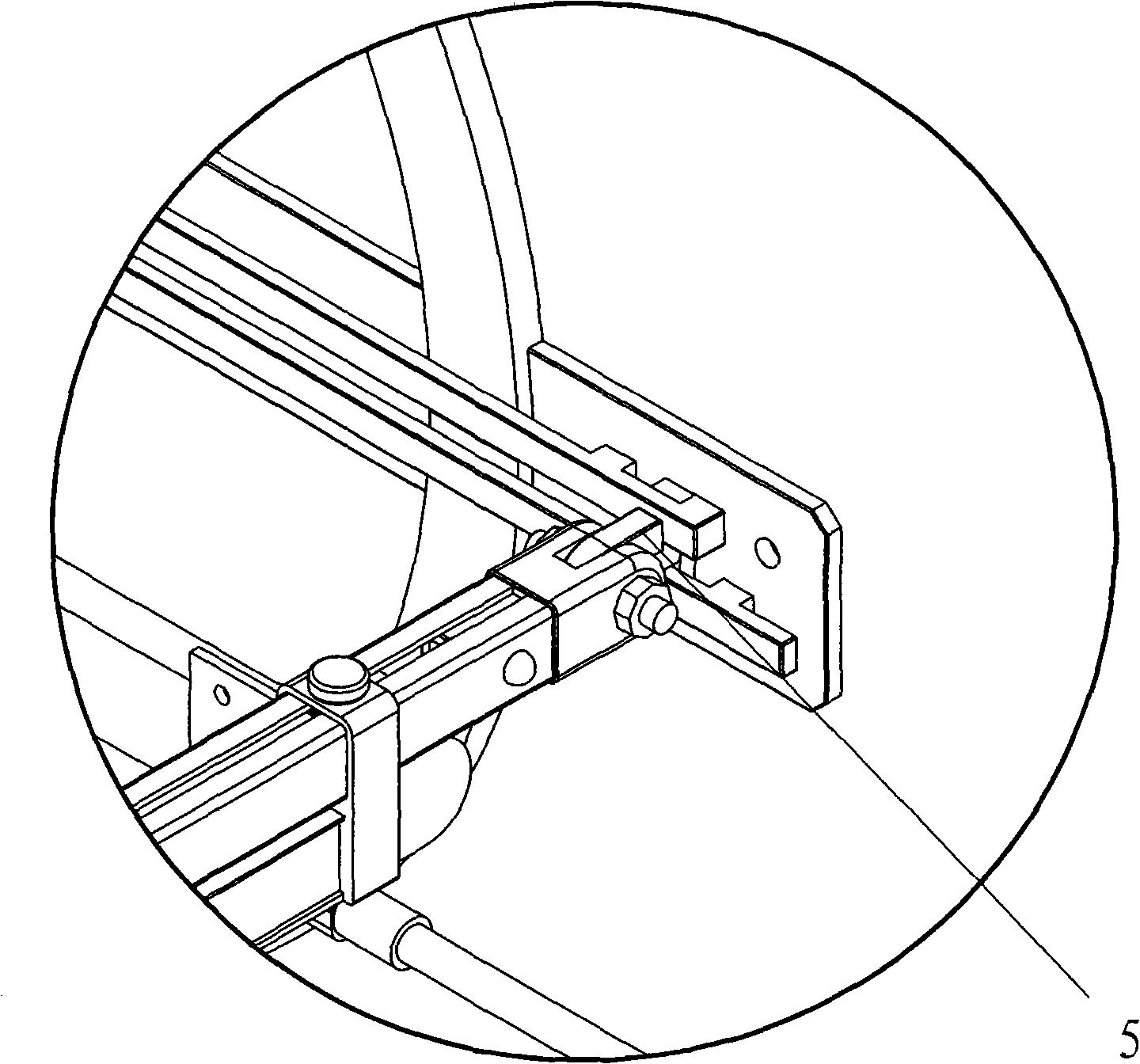
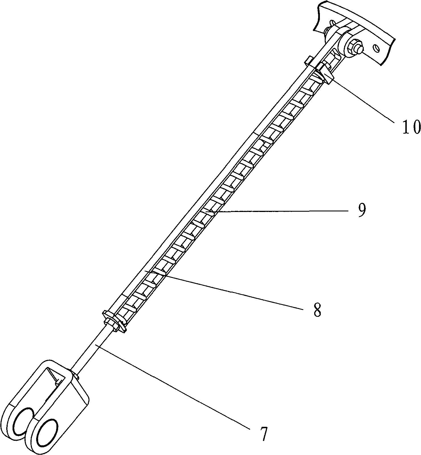
[0038] like Figure 1 to Figure 5 As shown, the mosquito net frame of the present invention includes a bracket component for hanging the mosquito net and a fixing component for fixing the bracket component. The fixing assembly includes a power frame 2 for hanging the bracket assembly, a fixing plate 3 for fixing the power frame 2 that can be fixed on the wall, and a pull rod 4 that can be fixed on the wall and connected with the power frame 2 . Between the fixed plate 3 and the power frame 2, there is a clamping piece 5 connecting the two, the clamping piece 5 is connected with the fixed plate 3 for lateral movement, and the clamping piece 5 is pivotally connected with the force frame 2; the fixed plate 3 is opened for The fixing plate 3 is installed in the hole on the wall, and the pull rod 4 is pivotally connected with the force frame 2 . The pull rod 4 includes a rod core 7, a rod sleeve 8, and a spring 9; one end of the rod core 7 is sleeved in the rod sleeve 8, and its e...
Embodiment 2
[0040] like Image 6 As shown, the only difference from Embodiment 1 is that the motor 61 is removed and replaced by a drag cable 71. When in use, as long as the drag cable 71 is pulled, the bracket can also be folded or opened.
Embodiment 3
[0042] The difference between this embodiment and the first embodiment lies in the bracket assembly. like Figure 7 to Figure 9As shown, a mosquito net frame, the bracket assembly of the mosquito net frame includes a bracket b 41 and a connecting piece b 42 for connecting the bracket b 41 and the power frame 2, and the connecting piece b 42 consists of a moving block 43 and a static block 44. The storage spring 45, the trigger spring piece 46 and the button 47 that can control the deformation of the trigger spring piece 46 are composed of; the moving block 43 is connected with the static block 44 connected to the force frame 2, and the two form a grippable The through hole of the bracket 1, the connecting part of the two is provided with a power storage spring 45 and a trigger spring piece 46, the trigger spring piece 46 can be stuck with the end of the moving block 43, and the button 47 is installed on the static block 44 and connected with the trigger spring Sheet 46 is in ...
PUM
 Abstract
Description
Claims
Application Information
 - R&D
- Intellectual Property
- Life Sciences
- Materials
- Tech Scout
- Unparalleled Data Quality
- Higher Quality Content
- 60% Fewer Hallucinations
Browse by: Latest US Patents, China's latest patents, Technical Efficacy Thesaurus, Application Domain, Technology Topic, Popular Technical Reports.
© 2025 PatSnap. All rights reserved.Legal|Privacy policy|Modern Slavery Act Transparency Statement|Sitemap|About US| Contact US: help@patsnap.com


