Cutting tool

A cutting tool and tool technology, applied in manufacturing tools, stone processing tools, metal sawing equipment, etc., can solve problems such as tool jamming, cutting edge breakage, downtime, etc.

Inactive Publication Date: 2010-03-03
TS TECNOSPAMEC
View PDF0 Cites 2 Cited by
  • Summary
  • Abstract
  • Description
  • Claims
  • Application Information

AI Technical Summary

Problems solved by technology

[0003] In order to use these systems, whether it is a blade-type saw blade, a disc-type blade or a milling cutter, the cutting edge needs to be firmly fixed and the part generated by the cut cannot be affected by the movement, because sometimes even small movements Can also result in cutting edge breakage and / or tool seizure with subsequent downtime

Method used


Image

  • Cutting tool
  • Cutting tool

Examples


Embodiment Construction

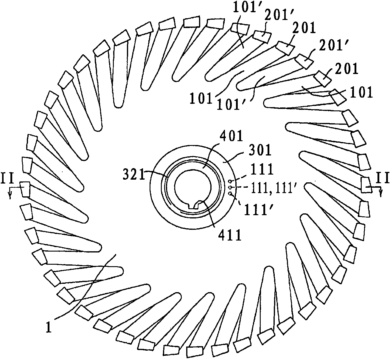
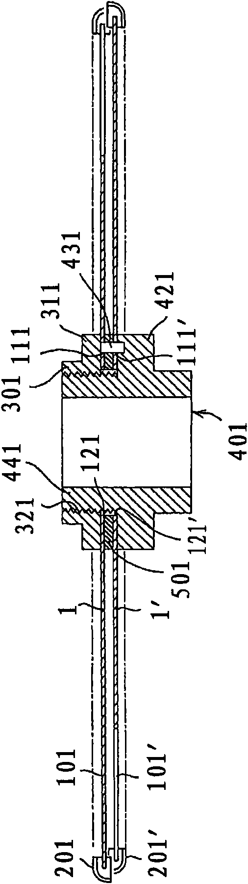
[0011] figure 1 A cutting tool according to the invention is shown; reference numeral 1 designates a structural element of said tool, said structural element comprising two discs 1 and 1' (cf. figure 2 ), a plurality of arms 101, 101' for supporting the cutting edges 201, 201' protrude from said two discs; in this case, the two discs 1, 1' are fixed on the sleeve 401 by means of screws The rings 301 are connected together. Inside the sleeve 401 there is also a radial cavity 411 which allows it to engage with a power take-off (not shown) of the operating device. Holes 111, 111' shown by dotted lines are formed in discs 1 and 1', respectively, from figure 2 As shown, it can be seen that the holes place the two disks opposite each other.

[0012] figure 2 shown figure 1 Tool cut along line II-II. It can be noted that, like the axial hole 121 of the disk 1, the disk 1' is positioned on the threaded sleeve 441 of the sleeve 401 by means of its axial hole 121'; the spacer r...


PUM


Abstract

Cutting tool comprising a structural member (1, 1') provided with means (301, 401 ) for engagement with operating means, and a plurality of cutting edges (201, 201') connected to said structural member (1, 1'), intended to follow a given cutting path; said cutting edges (201, 201') are each connected to said structural member (1, 1') by means of a suitable support part (101, 101') connected at oneend to said structural member (1, 1'), oriented in a manner substantially perpendicular to the plane of said cutting path and having said cutting edge (201, 201') at its free end, the cutting edges (201, 201') connected to two adjacent support parts being arranged in substantial opposition to each other with respect to said cutting path.

Description

technical field [0001] The present invention relates to tools, in particular to a cutting tool. Background technique [0002] Conventional blade-type tools, typically used to cut standard materials, must meet the following requirements: be designed with cutting edges (teeth or inserts) made of a material harder than the material being cut; Creates friction and removes a thin layer from the material being cut or "scrapes" the surface of the material being cut; has teeth shaped so as to create a gap or "track" that is larger than the cutting edge on the tool The thickness of the structural support section that travels after. [0003] In order to use these systems, whether it is a blade-type saw blade, a disc-type blade or a milling cutter, the cutting edge needs to be firmly fixed and the part generated by the cut cannot be affected by the movement, because sometimes even small movements It can also result in cutting edge breakage and / or tool seizure with subsequent downtime...

Claims


Application Information

Patent Timeline
IPC IPC(8): B23D61/02B23C5/00B28D1/04B23C5/08B28D1/12B23D49/00
CPCB23D61/026B23C5/006B28D1/048B23D49/003B28D1/121B23C5/08Y10T83/7809
Inventor P·马泰乌奇
Owner TS TECNOSPAMEC
Why Eureka
Try Eureka