Magnetic sensor

A magnetic sensor and magnetic detection technology, which is applied in the direction of measuring the geometric arrangement of magnetic sensing elements, instruments, and using electromagnetic devices for magnetic field measurement, etc., can solve the problems of different temperatures, large changes in resistance values, and inability to obtain suppression effects. Achieve high-precision magnetic detection and temperature uniformity

Inactive Publication Date: 2010-03-10
MURATA MFG CO LTD
View PDF5 Cites 12 Cited by
  • Summary
  • Abstract
  • Description
  • Claims
  • Application Information

AI Technical Summary

Problems solved by technology

Therefore, the temperature varies among the positions where the respective magnetoresistive elements are formed, and the effect of suppressing the influence of the resistance-temperature characteristic as described above cannot be obtained.
As a result, the variation in the resistance value among the plurality of magneto-resistive elements due to the difference in temperature increases, and the differential output fluctuates

Method used


Image

  • Magnetic sensor
  • Magnetic sensor
  • Magnetic sensor

Examples


Embodiment Construction

[0020]

A magnetic sensor according to a first embodiment of the present invention will be described with reference to the drawings.

[0021]

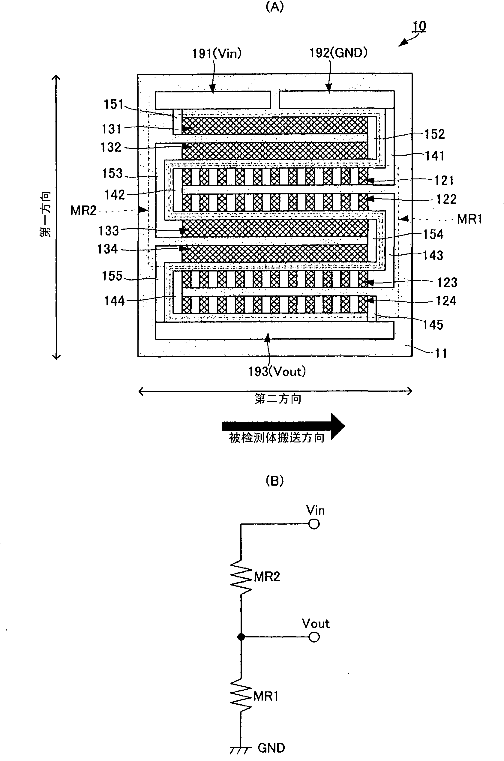
figure 1 (A) is a plan view showing the structure of the magnetic sensor 10 of this embodiment, figure 1 (B) is an equivalent circuit diagram of the magnetic sensor 10 .

[0022]

Such as figure 1 As shown in (A), the magnetic sensor 10 is constituted by forming a magnetically sensitive part on a substrate 11, connecting wire electrodes connected to the magnetically sensitive part, and external connection electrodes used for voltage input / output or ground connection. figure 1 (B) The circuit shown. That is, a circuit is configured in which the magnetoresistive elements MR1 ​​and MR2 are connected in series between the voltage input terminal Vin and the ground terminal GND, and the voltage output terminal Vout is connected to the connection point of the magnetoresistive elements MR1 ​​and MR2. Hereinafter, a specific structure is ...


PUM


Abstract

To provide a magnetic sensor having a structure that equalizes temperatures of a plurality of magnetoresistance elements. [Solving Means] Magnetic sensitive sections 121-124 forming a magnetoresistance element MR1 and magnetic sensitive sections 131-134 forming a magnetoresistance element MR2 are arranged on a substrate 11. The magnetic sensitive sections 121-124, and 131-134 are formed of elongated semiconductor layers, and the magnetic sensitive section 121-124 include shortening electrodes made of an electrically conductive material arranged at predetermined intervals on the semiconductor layers in the longitudinal direction thereof. The magnetic sensitive sections 121-124 and 131-134 are arranged close to each other with the longitudinal direction thereof in parallel to each other. Themagnetic sensitive sections 121-124 and 131-134 are arranged in the order of the magnetic sensitive sections 131 and 132 of the magnetoresistance element MR2, the magnetic sensitive sections 121 and122 of the magnetoresistance element MR1, the magnetic sensitive sections 133 and 134 of the magnetoresistance element MR2, the magnetic sensitive sections 123 and 124 of the magnetoresistance elementMR1.

Description

technical field [0001] The present invention relates to a magnetic sensor for detecting magnetic information such as a magnetic pattern possessed by an object to be detected. Background technique [0002] Conventionally, various magnetic sensors have been proposed that detect a magnetic pattern or magnetic information incorporated in a detection object such as a banknote. [0003] For example, Patent Document 1 discloses a general differential magnetic sensor configured by forming a curved magnetoresistance effect film on a substrate. In addition, Patent Document 2 also discloses a differential magnetic sensor including a plurality of magnetoresistive elements. Here, more specifically, as shown in FIG. 24 of Patent Document 2, each magnetoresistive element has a plurality of elongated magnetically sensitive parts, and the plurality of magnetically sensitive parts are aligned in one direction within the detection range of the object to be detected. arranged in series ...

Claims


Application Information

Patent Timeline
IPC IPC(8): G01R33/09G01R35/00
CPCG01R33/093G01R33/0005B82Y25/00G01R33/06G01R33/09
Inventor 南谷保
Owner MURATA MFG CO LTD
Why Eureka
Try Eureka