
Replaceable key lock core with foolproof function

A function, key lock technology, applied in the field of replaceable key lock cores, can solve problems such as inability to open, general products without suitable structure, and inconvenience

Active Publication Date: 2012-06-13
TAIWAN FU HSING INDAL
View PDF4 Cites 0 Cited by
  • Summary
  • Abstract
  • Description
  • Claims
  • Application Information

AI Technical Summary

Problems solved by technology

[0002] see figure 1 As shown, it is a flow chart of changing the key steps of a conventionally known replaceable key lock core, which consists of figure 1 It can be seen that the most important operation step in the existing known key replacement process is to apply a thrust to the first matching key to displace the slider and drive the first gear to disengage from the second gear and rotate the second gear. Match the lock key (new key) to reset the slider and drive the first gear to re-engage with the second gear. The key (new key) is inserted into the position and the lock core is rotated, resulting in the inability to open when using the new key. Therefore, how to ensure that the key is fully inserted in the state before the key can be replaced is the structural design of the replaceable key core. A very important topic
[0003] It can be seen that the above-mentioned existing replaceable key lock core obviously still has inconvenience and defects in structure and use, and needs to be further improved urgently.
In order to solve the above-mentioned problems, the relevant manufacturers have tried their best to find a solution, but for a long time no suitable design has been developed, and the general product has no suitable structure to solve the above-mentioned problems. This is obviously the relevant industry. Urgent problem

Method used


Image

  • Replaceable key lock core with foolproof function
  • Replaceable key lock core with foolproof function
  • Replaceable key lock core with foolproof function

Examples


Embodiment Construction

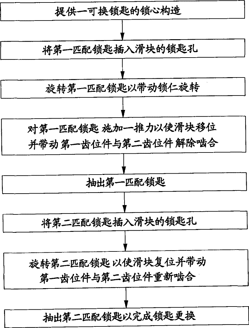
[0057] In order to further explain the technical means and effects of the present invention to achieve the intended purpose of the invention, the specific implementation of the replaceable key lock core with foolproof function proposed according to the present invention, Structure, characteristic and effect thereof are as follows in detail.

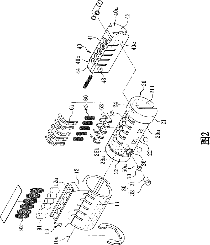
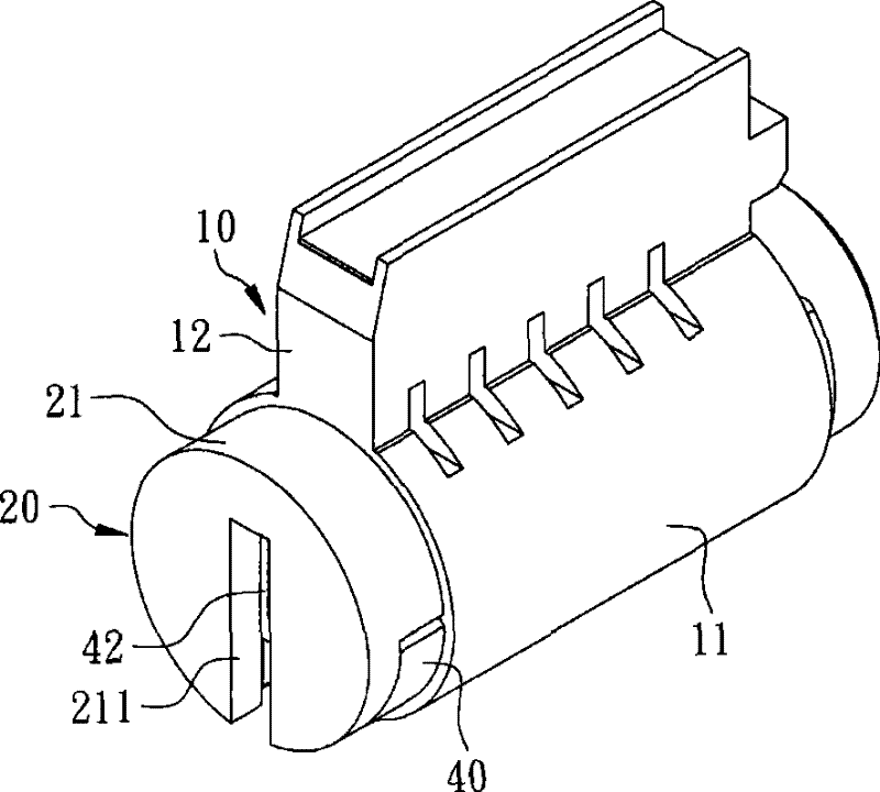
[0058] see figure 2 and image 3 Shown is a preferred embodiment of the present invention, an exploded perspective view and an assembled perspective view of a replaceable key lock core with foolproof function. A replaceable key lock core with fool-proof function according to a preferred embodiment of the present invention includes a lock case 10, a lock core 20, a limiting member 30, a slider 40, a driving member 50 and a plurality of tooth position members Group 60, the lock housing 10 has a hollow cylindrical portion 11, an extending convex portion 12 formed on one side of the hollow cylindrical portion 11 and defines a central axis ...


PUM


Abstract

The invention relates to a replaceable key lock core with foolproof function, comprising a lock case, a lock insert, a limiting piece, a slide block, a driving piece and a plurality of tooth position piece sets. The lock case is provided with a hollow cylindrical part; the lock insert is arranged in the hollow cylindrical part and provided with an accommodating groove, a plurality of first tooth position piece sliding chutes and a first punch hole; the limiting piece is arranged in the first punch hole; the slide block is arranged in the accommodating groove and is provided with a plurality of second tooth position piece sliding chutes, a key hole communicated with the second tooth position piece sliding chutes and a second punch hole communicated with the key hole, wherein the second punch hole corresponds to the first punch hole; the driving piece is arranged in the second punch hole and one end of the limiting piece is supported against the driving piece; and each tooth position piece set is arranged in the first tooth position piece sliding chutes and the second tooth position piece sliding chutes and at least comprises a first tooth position piece and a second tooth position piece.

Description

technical field [0001] The invention relates to a lock core structure, in particular to a replaceable key lock core with foolproof function. Background technique [0002] see figure 1 As shown, it is a flow chart of changing the key steps of a conventionally known replaceable key lock core, which consists of figure 1 It can be seen that the most important operation step in the existing known key replacement process is to apply a thrust to the first matching key to displace the slider and drive the first gear to disengage from the second gear and rotate the second gear. Match the lock key (new key) to reset the slider and drive the first gear to re-engage with the second gear. The key (new key) is inserted into the position and the lock core is rotated, resulting in the inability to open when using the new key. Therefore, how to ensure that the key is fully inserted in the state before the key can be replaced is the structural design of the replaceable key core. An extreme...

Claims


Application Information

Patent Timeline
Patent Type & Authority Patents(China)
IPC IPC(8): E05B31/00
Inventor 黄莲溪谢秉宏
Owner TAIWAN FU HSING INDAL
Features
  • Generate Ideas
  • Intellectual Property
  • Life Sciences
  • Materials
  • Tech Scout
  • Unparalleled Data Quality
  • Higher Quality Content
  • 60% Fewer Hallucinations
Learn More