
Electrical connector assembly

An electrical connector, plug connector technology, applied in the direction of connection, two-part connection device, parts of the connection device, etc., can solve the problem of heat dissipation of the unsolved power connector, and cannot guarantee the stable contact between the first terminal and the second terminal. , affecting the function of the connector, etc.

Active Publication Date: 2018-12-18
DEYI PRECISION ELECTRONIC IND CO LTD PANYU
View PDF7 Cites 0 Cited by
  • Summary
  • Abstract
  • Description
  • Claims
  • Application Information

AI Technical Summary

Problems solved by technology

[0002] A known power connector combination, the plug connector includes a first body and a first terminal accommodated in the first body, the socket connector includes a second body and a second terminal accommodated in the second body, the second body There is a partition that separates each second terminal and completely closes it. In order to guide the correct insertion of the plug connector, a narrow slot is usually opened on the partition of the socket connector or in the second body receiving cavity. The edge is chamfered, and the corresponding ridges and chamfers are set on the plug connector to match the narrow groove. However, the power connector usually carries a relatively large current or power, which will generate considerable heat during use. The conventional design above can only achieve foolproofing but does not solve the heat dissipation problem of the power connector
At the same time, the first terminal of the plug connector usually has a pair of interfaces and a main body, and the opposite sides of the main body respectively extend an elastic arm to the direction of the interface for docking with the second terminal. However, since each elastic arm has only One contact part, so it can only be in contact with the two surfaces of the second terminal, so the stable contact between the first terminal and the second terminal cannot be guaranteed during the docking process, which will easily affect the function of the connector; in addition, because the contact part is only It is located near the mating port, but no elastic contact part is provided at the rear of the mating port close to the direction of the main body, so it cannot provide sufficient insertion force during the mating process of the connector, which may easily lead to falling off during use and affect the use effect

Method used


Image

  • Electrical connector assembly
  • Electrical connector assembly
  • Electrical connector assembly

Examples


Embodiment Construction

[0044] In order to facilitate a better understanding of the purpose, structure, features, and effects of the present invention, the present invention will now be further described in conjunction with the accompanying drawings and specific embodiments.

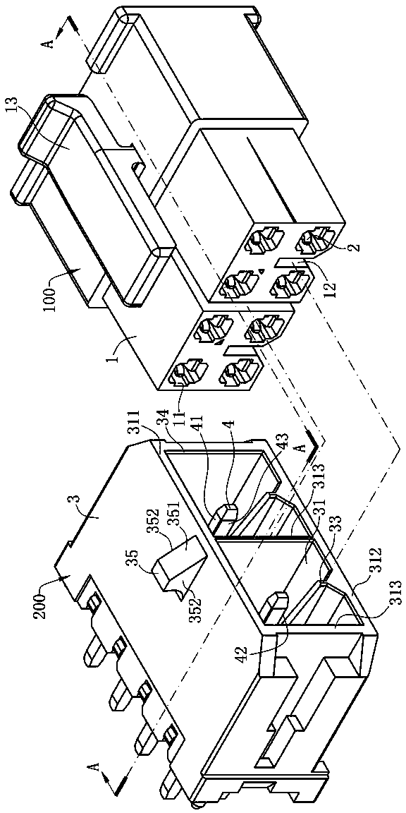
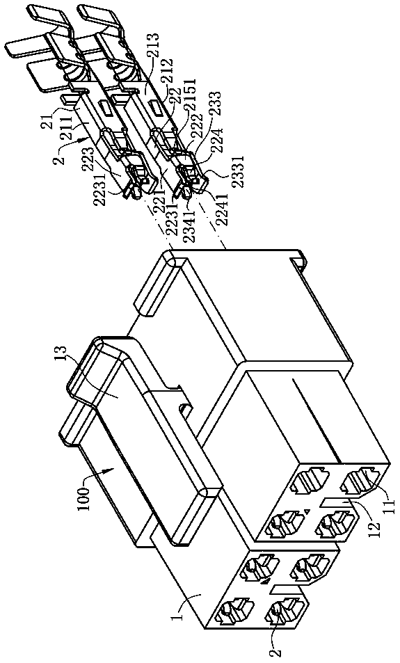
[0045] Please refer to Figure 1 to Figure 9 , is a main embodiment of an electrical connector combination of the present invention, which includes a plug connector 100 and a socket connector 200 .

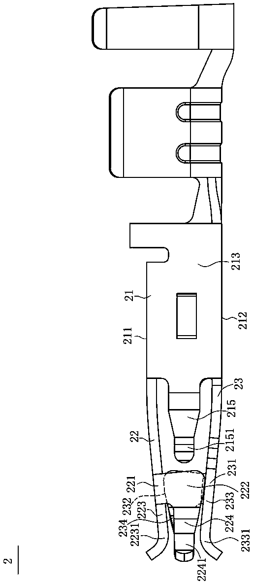
[0046] Please refer to Figure 1 to Figure 9 , the plug connector 100 includes a first body 1 and a plurality of first terminals 2 . The first body 1 has four receiving holes 11 divided into upper and lower rows, each row has two receiving holes 11, and a slot 12 is arranged between the two receiving holes 11 in the lower row. The first body 1 is provided with a locking arm 13 on a side away from the hole 12 outside the receiving hole 11 , and the locking arm 13 is perpendicular to the hole 12 . A plurality of first terminals 2...


PUM


Abstract

An electrical connector assembly is disclosed, which includes plug connector having a first body and first terminals accommodated therein, and a socket connector. A slot is arranged between the two first terminals, each first terminal has a first contact arm and a second contact arm which are oppositely arranged, each of the first contact arm and the second contact arm is provided with first, second, third, and fourth contact parts, and a fifth contact part is further provided behind the second contact portion. The socket connector has a second body and second terminals accommodated therein, abarrier stretches from one side of the second body to between the two second terminals, when the plug connector is in a butt joint with the socket connector, the barrier is matched with the slot, andthe second terminals are first in contact with the first, second, third and fourth contact parts, and is in contact with the fifth contact part in the process of further insertion, thereby ensuring the correct butt joint of the plug connector and the socket connector, and the first terminal and the second terminal are in stable contact and not easy to fall off.

Description

technical field [0001] The invention relates to an electrical connector combination, in particular to an electrical connector combination which has a good heat dissipation effect and can ensure correct insertion of butt connectors and stable contact. Background technique [0002] A known power connector combination, the plug connector includes a first body and a first terminal accommodated in the first body, the socket connector includes a second body and a second terminal accommodated in the second body, the second body There is a partition that separates each second terminal and completely closes it. In order to guide the correct insertion of the plug connector, a narrow slot is usually opened on the partition of the socket connector or in the second body receiving cavity. The edge is chamfered, and the corresponding ridges and chamfers are set on the plug connector to match the narrow groove. However, the power connector usually carries a relatively large current or power...

Claims


Application Information

Patent Timeline
Patent Type & Authority Applications(China)
IPC IPC(8): H01R13/02H01R13/193H01R13/46H01R13/64H01R24/00
CPCH01R13/02H01R13/193H01R13/46H01R13/64H01R24/005
Inventor 罗国强何东明林庆其
Owner DEYI PRECISION ELECTRONIC IND CO LTD PANYU
Features
  • Generate Ideas
  • Intellectual Property
  • Life Sciences
  • Materials
  • Tech Scout
  • Unparalleled Data Quality
  • Higher Quality Content
  • 60% Fewer Hallucinations
Learn More