
Electronic device and machine table used in cooperation with same

一种电子装置、电连接器的技术,应用在连接装置的零部件、耦合装置、变电站/开关布置细节等方向,能够解决不能应用成品、牵涉因素广、出货控管、品质和成本错综复杂等问题

Active Publication Date: 2021-05-14
DELTA ELECTRONICS INC
View PDF7 Cites 0 Cited by
  • Summary
  • Abstract
  • Description
  • Claims
  • Application Information

AI Technical Summary

Problems solved by technology

However, the foregoing existing practice cannot be applied to finished products that have already been sold
If the aforementioned existing practice is to be applied to these finished products, it must be re-modified for each finished product shell
However, if there are as many as dozens of types of finished products that have already been sold, the factors involved will be too wide, which may cause intricate problems such as shipment control, quality and cost.

Method used


Image

  • Electronic device and machine table used in cooperation with same
  • Electronic device and machine table used in cooperation with same
  • Electronic device and machine table used in cooperation with same

Examples


Embodiment Construction

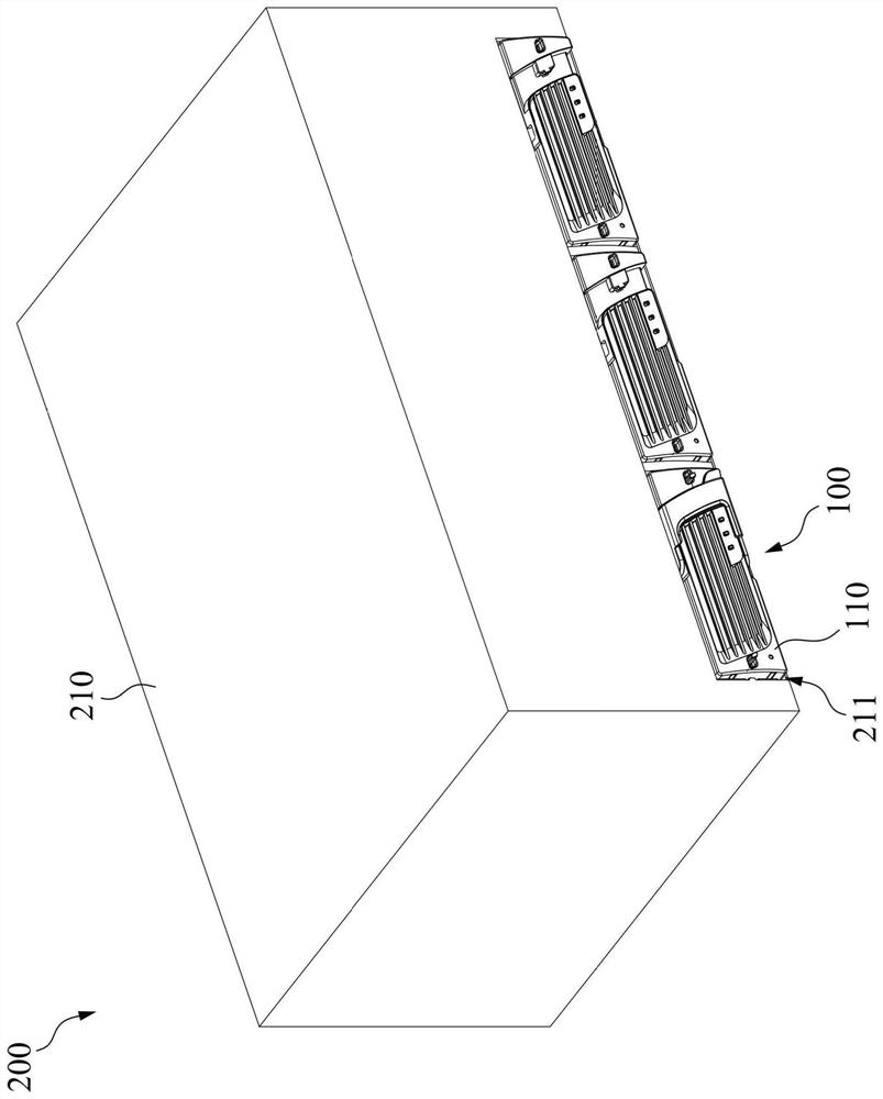
[0036] Please refer to figure 1 . figure 1 It is a three-dimensional combined view showing the electronic device 100 and the machine 200 according to an embodiment of the present invention. like figure 1 As shown, in this embodiment, the electronic device 100 includes a first body 110 . The machine 200 includes a second body 210 . The second body 210 has a slot 211 . The slot 211 is configured for insertion of the electronic device 100 . In some implementations, the machine 200 is, for example, a charger. In some embodiments, the electronic device 100 is, for example, a rectifier, an inverter, a converter or a solar charger, but the invention is not limited thereto. The structure, function and connection relationship between the components included in the electronic device 100 and the machine 200 will be described in detail below.

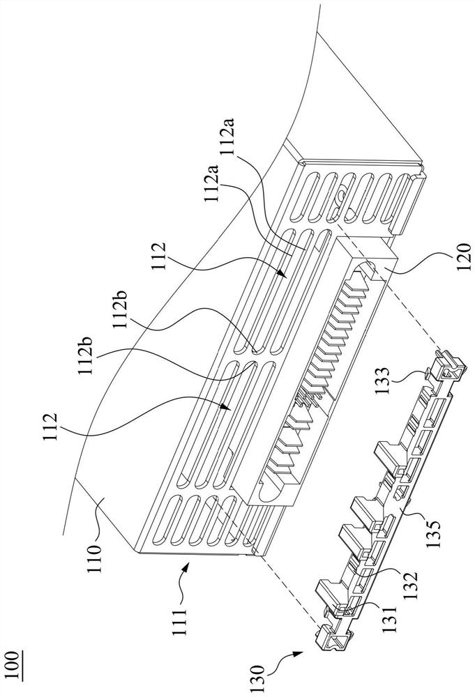
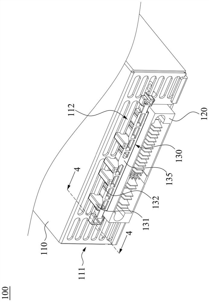
[0037] Please refer to Figure 2A as well as Figure 2B . Figure 2A It is a perspective view illustrating the electronic device 100 acc...


PUM


Abstract

The invention discloses an electronic device and a machine table used in cooperation with the electronic device. The electronic device comprises a first body, a first electric connector and an insert. The first body is provided with an insertion end and at least one hole located in the insertion end. The first electric connector is arranged at the insertion end. The insert is connected with the first body through at least one hole and comprises a plurality of ribs and a plurality of removing parts. The ribs and the removal portions are linearly arranged in order based on a coding mode. The rib extends away from the insertion end.

Description

technical field [0001] The invention relates to an electronic device and a machine used in conjunction with it, in particular to an electronic device and a machine for its insertion. Background technique [0002] Generally speaking, the male and female parts that can be plugged and combined with each other are usually designed with a fool-proof design to prevent problems such as assembly errors or component damage. One existing practice is to make differentiation on the shell. That is to say, when manufacturing the male part and the female part, a specific shell is directly manufactured, and corresponding fool-proof mechanisms are made respectively. However, the aforementioned existing practices cannot be applied to finished products that have been sold. If the aforementioned existing practice is to be applied to these finished products, it is necessary to re-modify the shell of each finished product. However, if there are as many as dozens of types of finished products t...

Claims


Application Information

Patent Timeline
Patent Type & Authority Applications(China)
IPC IPC(8): H05K7/14
CPCH05K7/1438H05K7/1432H05K7/1455H01R13/6456H02B1/46H05K5/0217
Inventor 林正淳
Owner DELTA ELECTRONICS INC
Features
  • Generate Ideas
  • Intellectual Property
  • Life Sciences
  • Materials
  • Tech Scout
  • Unparalleled Data Quality
  • Higher Quality Content
  • 60% Fewer Hallucinations
Learn More