
Replaceable key core

A key lock and key technology, applied in the field of replaceable key lock cores, can solve the problems such as the key replacement procedure has not been completed, the general product does not have a suitable structure, and the lock cannot be unlocked normally.

Active Publication Date: 2013-04-17
TAIWAN FU HSING INDAL
View PDF2 Cites 0 Cited by
  • Summary
  • Abstract
  • Description
  • Claims
  • Application Information

AI Technical Summary

Problems solved by technology

However, in the conventional design of the replaceable key core structure, it may be because the general user does not insert the new key into the position and then rotate the lock core during the step of replacing the new key, resulting in the replacement of the key before the actual completion of the key replacement. Before the program, the new key is rotated, which causes the subsequent user to use the new key to insert it to the position (that is, insert it to the end) and still fail to open the lock normally. Therefore, how to ensure that the user must insert the new key to the position (i.e. Only when the key is inserted to the end) can the key be replaced, which is an extremely important issue in the structural design of the replaceable key core.
[0003] It can be seen that the above-mentioned existing replaceable key lock core obviously still has inconvenience and defects in structure and use, and needs to be further improved urgently.
In order to solve the above-mentioned problems, the relevant manufacturers have tried their best to find a solution, but for a long time no suitable design has been developed, and the general product has no suitable structure to solve the above-mentioned problems. This is obviously the relevant industry. Urgent problem

Method used


Image

  • Replaceable key core
  • Replaceable key core
  • Replaceable key core

Examples


Embodiment Construction

[0060] In order to further explain the technical means and effects of the present invention to achieve the intended purpose of the invention, in conjunction with the accompanying drawings and preferred embodiments, the specific implementation, structure, features and Efficacy, as detailed below.

[0061] The foregoing and other technical contents, features and effects of the present invention will be clearly presented in the following detailed description of the preferred embodiment with reference to the drawings. Through the description of the specific embodiments, the technical means and effects of the present invention to achieve the predetermined purpose can be understood more deeply and concretely. However, the accompanying drawings are only for reference and explanation, and are not used to describe the present invention. limit.

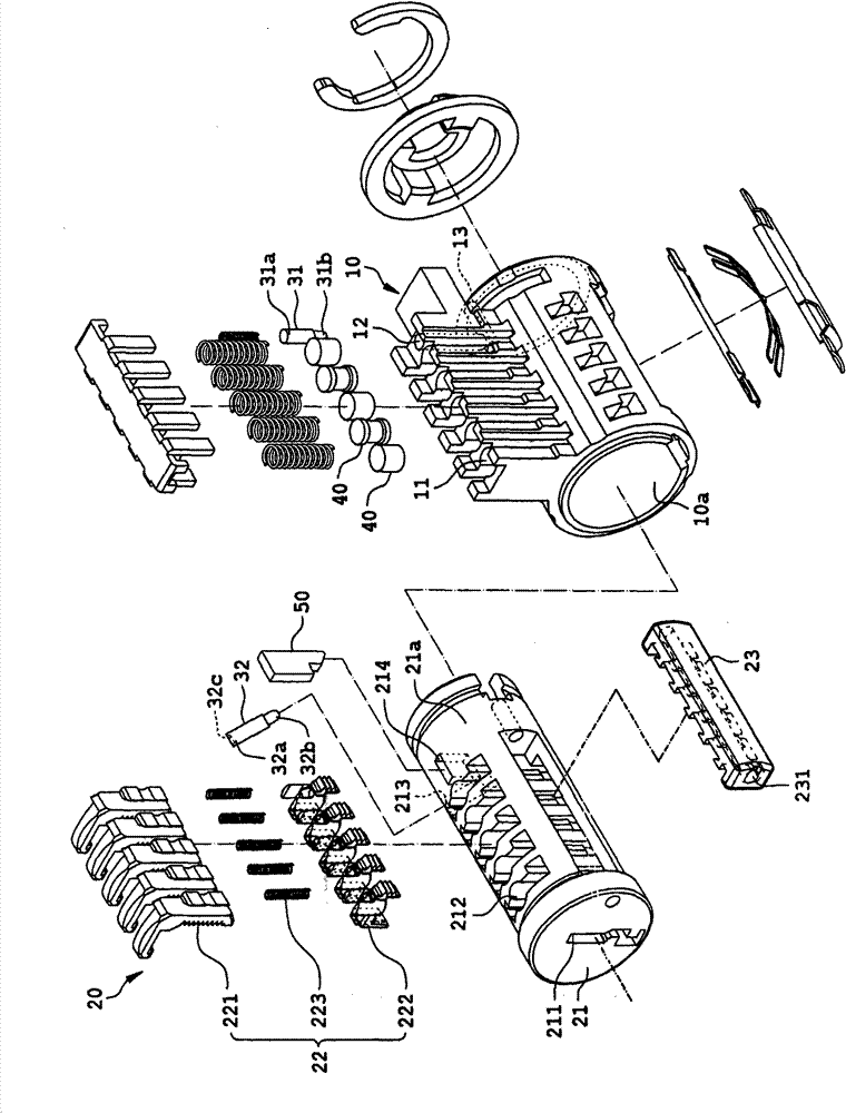
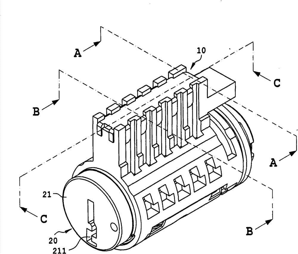
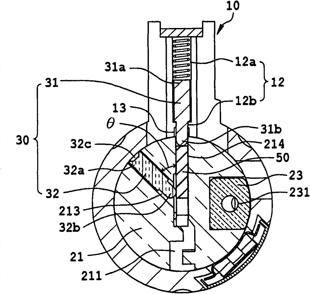
[0062] See figure 1 , figure 2 and image 3 As shown, which is a preferred embodiment of the present invention, a replaceable key lock core inclu...


PUM


Abstract

The invention relates to a replaceable key core, which comprises a lock case, a lock kernel set and a fool-proof assembly, wherein the lock kernel set is arranged in the lock case; the lock case is provided with a plurality of upper lock ball holes and a straight groove; the lock kernel set comprises a lock kernel body, a plurality of combined lock balls and a positioning block arranged in the lock kernel body; the lock kernel body is provided with an outer side wall, a key hole, a plurality of lower lock ball holes and a through hole for communicating the outer side wall with the key hole; the combined lock balls are arranged in the lower lock ball holes of the lock kernel body respectively; the fool-proof assembly comprises a limiting part and a resisting part; the limiting part is arranged in the straight groove of the lock case; the resisting part is arranged in the through hole of the lock kernel body; and the limiting part can be pressed against the resisting part.

Description

Technical field [0001] The invention relates to a key lock core, in particular to a replaceable key lock core. Background technique [0002] Existing conventional replaceable key cores, such as the replaceable key cores disclosed in US Published Patent No. US6860131 and US Published Patent No. US20090277240, must be inserted into the position in the step of replacing the new key. (Insert it to the end), and then rotate the new key to complete the key replacement procedure. However, the existing conventional replaceable key lock core structure design may cause the general user to rotate the lock core without inserting the new key into the position in the step of replacing the new key, resulting in the fact that the key replacement has not been completed yet. Before the procedure, the new key is rotated, and subsequent users use the new key to insert the new key into the position (that is, insert it to the end), but still cannot unlock the lock normally. Therefore, how to ensure t...

Claims


Application Information

Patent Timeline
Patent Type & Authority Patents(China)
IPC IPC(8): E05B27/04E05B35/08
Inventor 黄昭铭陈吉明
Owner TAIWAN FU HSING INDAL
Features
  • Generate Ideas
  • Intellectual Property
  • Life Sciences
  • Materials
  • Tech Scout
  • Unparalleled Data Quality
  • Higher Quality Content
  • 60% Fewer Hallucinations
Learn More