Method for detecting transmission line fault direction

A technology for transmission lines and fault directions, applied in directions such as fault locations, can solve the problems that current fault transient traveling wave fault direction detection and direction protection cannot be realized, and voltage fault transient traveling wave wave head transmission cannot be changed.

Active Publication Date: 2010-05-05
TSINGHUA UNIV
View PDF0 Cites 29 Cited by
  • Summary
  • Abstract
  • Description
  • Claims
  • Application Information

AI Technical Summary

Problems solved by technology

However, existing studies have shown that current transformers used in power systems can effectively transmit transient traveling waves of current faults. Capacitive voltage transformers, which are widely used in power systems with 220kV and above voltage levels, only It can transmit and change the voltage signal of a very narrow frequency band around the working frequency (50 Hz or 60 Hz), and cannot effectively transfer t...

Method used


Image

  • Method for detecting transmission line fault direction
  • Method for detecting transmission line fault direction
  • Method for detecting transmission line fault direction

Examples


Embodiment Construction

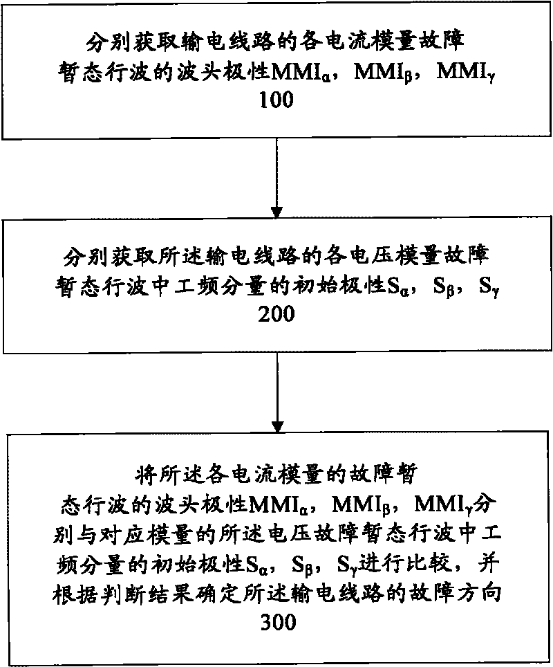
[0027] figure 1 A flow chart of a method for detecting a fault direction of a transmission line according to an embodiment of the present invention is shown. The method for detecting the fault direction of the transmission line includes: step 100, respectively obtaining the wave head polarity MMI of the three current modulus fault transient traveling waves of the transmission line α , MMI β , MMI γ ; Step 200, respectively obtain the initial polarity S of the power frequency component in the three voltage modulus fault transient traveling waves of the transmission line α , S β , S γ ; Step 300, the wave head polarity MMI of each current modulus fault transient traveling wave α , MMI β , MMI γ Respectively with the initial polarity S of the power frequency component in the voltage fault transient traveling wave corresponding to the modulus α , S β , S γ making a comparison, and determining the fault direction of the transmission line according to the judgment result. ...


PUM


Abstract

The invention provides a method for detecting transmission line fault direction, and comprises: step 100, respectively obtaining wave-head polarities (MMI alpha, MMI beta and MMI gamma) of three modulus current fault transient state travelling waves of a power transmission line; step 200, respectively obtaining initial polarities (S alpha, S beta, and S gamma) of power frequency components in the three modulus current fault transient state travelling waves of the power transmission line; and step 300, respectively comparing the wave-head polarities (MMI alpha, MMI beta and MMI gamma) of three modulus current fault transient state travelling waves with the initial polarities (S alpha, S beta, and S gamma) of power frequency components in the three modulus current fault transient state travelling waves, and determining the fault direction of the power transmission line according to the judgment result. The invention solves the long-standing difficulty that travelling wave fault direction detecting elements applied in actual power systems and the travelling wave direction is hard to realize which are caused by capacitive voltage transformer can not transmit and transform the wave-head of voltage fault transient state travelling wave.

Description

technical field [0001] The invention relates to the technical field of relay protection and fault detection of power systems, in particular to the field of fault direction detection of power transmission lines. Background technique [0002] The parameters of high-voltage transmission lines, especially EHV and UHV long-distance transmission lines, have obvious distribution parameter characteristics. The traditional relay protection based on power frequency electrical quantities is affected by factors such as the distributed capacitance of the transmission line and the saturation of the current transformer, and cannot accurately detect faults on the line. But in fact, the fault transient traveling wave after the fault contains a wealth of fault information. The voltage fault transient traveling wave head and current fault transient traveling wave head signal after a fault is a signal with a wide spectrum range, and it is a signal of the whole frequency domain in theory. As e...

Claims


Application Information

Patent Timeline
IPC IPC(8): G01R31/08
Inventor 董新洲施慎行王宾王世勇
Owner TSINGHUA UNIV
Why Eureka
Try Eureka