Transmission line malfunction directional element

A technology for transmission lines and fault directions, applied in directions such as fault locations, can solve the problems of current fault transient traveling wave fault direction detection and directional protection cannot be realized.

Active Publication Date: 2010-05-19
TSINGHUA UNIV
View PDF0 Cites 11 Cited by
  • Summary
  • Abstract
  • Description
  • Claims
  • Application Information

AI Technical Summary

Problems solved by technology

However, the existing research shows that the current transformer used in the power system can effectively transmit the transient traveling wave of the fault current, and the voltage transformer widely used in the power system 220kV and above voltage level - capacitive voltage transformer, It can only transmit and transform the voltage signal of a very narrow frequency band around the operating frequency of the power system (50Hz or 60Hz), and cannot effe

Method used


Image

  • Transmission line malfunction directional element
  • Transmission line malfunction directional element
  • Transmission line malfunction directional element

Examples


Embodiment Construction

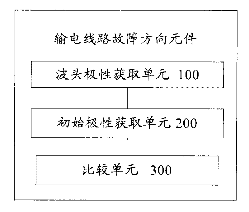
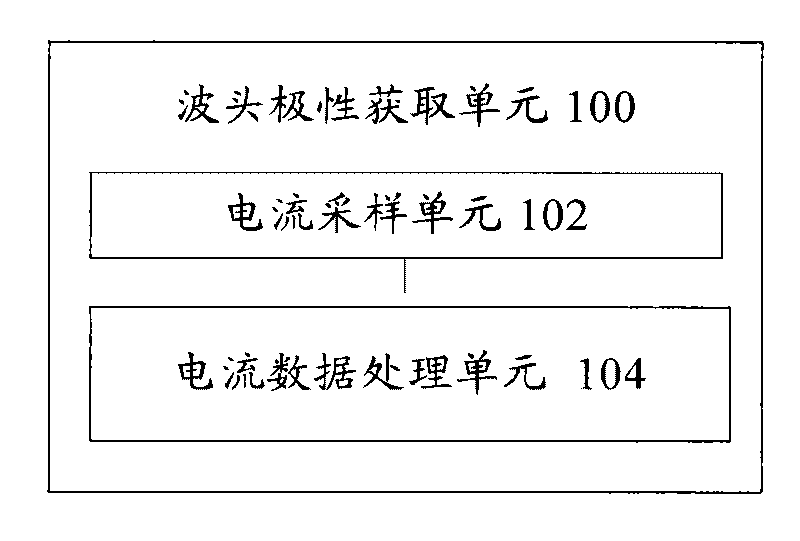
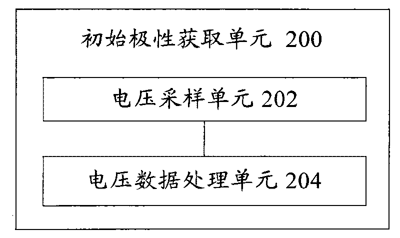
[0024] figure 1 A structural diagram of a transmission line fault directional element according to an embodiment of the present invention is shown. The fault direction element of the transmission line includes: a wave head polarity acquisition unit 100, which respectively obtains the wave head polarity MMI of each current modulus fault transient traveling wave of the transmission line α , MMI β , MMI γ The initial polarity acquisition unit 200 obtains the initial polarity S of the power frequency component in each voltage modulus fault transient traveling wave of the transmission line respectively α , S β , S γ ; Comparing unit 300, with the wave head polarity MMI of each current modulus fault transient traveling wave α , MMI β , MMI γ The initial polarity of the power frequency component in the voltage fault transient traveling wave corresponding to the modulus is compared respectively, and the fault direction of the transmission line is determined according to the jud...


PUM


Abstract

The invention provides a transmission line malfunction directional element, comprising a wavefront polarity acquisition unit 100, an initial polarity acquisition unit 200 and a comparison unit 300, wherein the wavefront polarity acquisition unit 100 is used for acquiring the wavefront polarity MMIalpha, MMIbeta and MMIgamma from three current modulus malfunction transient travelling wave of a transmission line; the initial polarity acquisition 200 unit is used for acquiring the initial polarity Salpha, Sbeta and Sgamma from power frequency components of the three current modulus malfunction transient travelling wave; and the comparison unit 300 is used for comparing the wavefront polarity MMIalpha, MMIbeta and MMIgamma of the three current modulus malfunction transient travelling waves with the initial polarity of the power frequency of the voltage malfunction transient travelling wave of the corresponding modulus respectively and determining the malfunction direction of the transmission line according to the judgment result, thus solving the problem that the travelling wave malfunction directional element and travelling wave directional protection capable of being applied in the actual power system can not be formed for a long time due to that the capacitor voltage transformer is unable to transmit the wavefront of the transient voltage malfunction travelling wave.

Description

technical field [0001] The invention relates to the technical field of relay protection and fault detection of power systems, in particular to the field of fault direction detection of power transmission lines. Background technique [0002] The parameters of high-voltage transmission lines, especially EHV and UHV long-distance transmission lines, have obvious distribution parameter characteristics. The traditional relay protection based on power frequency electrical quantities is affected by factors such as the distributed capacitance of the transmission line and the saturation of the current transformer, and cannot accurately detect faults on the line. But in fact, the fault transient traveling wave after the fault contains a wealth of fault information. The voltage fault transient traveling wave head and current fault transient traveling wave head signal after a fault is a signal with a wide spectrum range, and it is a signal of the whole frequency domain in theory. As e...

Claims


Application Information

Patent Timeline
IPC IPC(8): G01R31/08
Inventor 董新洲王世勇施慎行王宾
Owner TSINGHUA UNIV
Why Eureka
Try Eureka