Electrical connector and sealing ring thereof

A technology of electrical connectors and sealing rings, which is applied in the field of sealing rings and can solve problems such as easy damage

Active Publication Date: 2010-05-26
胡连电子(南京)有限公司 +1
2 Cites 14 Cited by

AI-Extracted Technical Summary

Problems solved by technology

[0006] The obvious deficiency of the above-mentioned patent is that the flange of the plug part is thin and ...

Abstract

The invention discloses an electric connector which consists of a casing body, a sealing ring and a grid element. The upper part of the casing body is provided with a joining part, the lower part is connected with a containing space of which the bottom is provided with an opening, and the inner wall of the top is convexly provided with an annular first positioning flange. The sealing ring comprises a plug element which is sleeved in the containing space, and areas among the outer walls of the top and the bottom and a through hole are respectively provided with a first annular circumferential positioning groove and a second annular circumferential positioning groove in the axial direction. The grid element is sleeved in the containing space, and the top surface of the grid element is convexly provided with a second positioning flange corresponding to the second circumferential positioning groove. When the grid element and the containing space of the casing body form locking, the plug element is pushed by the grid element, the first circumferential positioning groove and the second circumferential positioning groove are respectively spliced in the first positioning flange of the casing body and the second positioning flange of the grid element, and then the circumferential outer wall of the plug element protrudes and deforms outwards, and clings to the circumferential inner wall of the containing space.

Application Domain

Couplings bases/cases

Technology Topic

EngineeringUpper segment +2

Image

  • Electrical connector and sealing ring thereof
  • Electrical connector and sealing ring thereof
  • Electrical connector and sealing ring thereof

Examples

  • Experimental program(2)

Example Embodiment

[0040] Example 1:
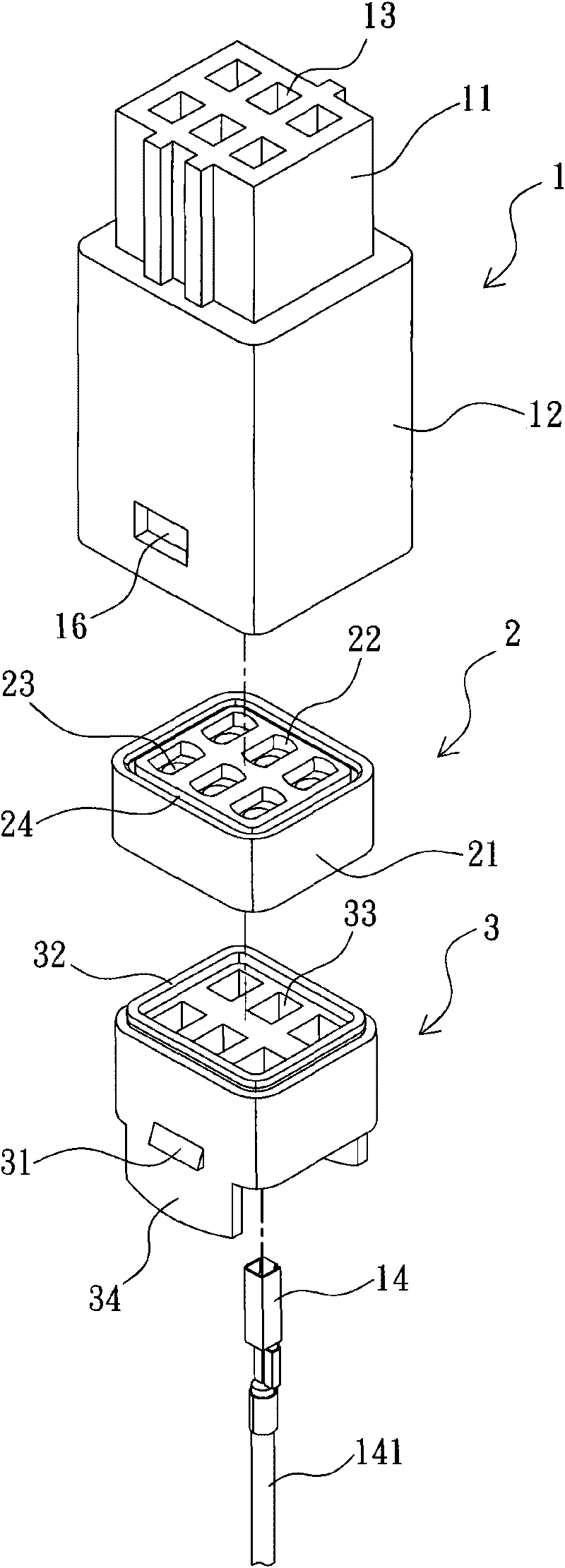
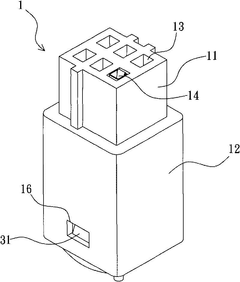
[0041] Such as Figure 1a to Figure 3b As shown, basically, the first embodiment of the electrical connector of the present invention is composed of a housing 1, a sealing ring 2, and a grid member 3.
[0042] Wherein, the housing 1 is made of insulating material, such as plastic, and its upper section has a joint 11, and a larger skirt 12 is integrally connected below the joint 11, and an accommodating space 121 is provided inside the skirt 12 , In order to accommodate and lock the sealing ring 2 and the grille 3 later. The joint portion 11 is used for the butt connection of another electrical connector. Therefore, the joint portion 11 axially defines more than one terminal slot 13 communicating with the accommodating space 121 for the terminal 14 to be accommodated and positioned. The wire 141 of 14 passes through the sealing ring 2 and the grid member 3. In addition, an annular first positioning flange 15 protrudes from the inner wall of the top of the accommodating space 121 so as to engage with the corresponding groove of the sealing ring 2.
[0043] In order to prevent the grille element 3 from being axially detached from the bottom opening of the skirt portion 12 of the housing 1, a locking mechanism is provided between the two. For example, the two opposite walls of the skirt portion 12 are provided with buckle grooves 16, while the two opposed outer walls of the grille element 3 are A beveled protrusion 31 is projected. When the pair of protrusions 31 are buckled in the buckle groove 16, they are formed as Figure 3b The locked relationship shown.
[0044] The sealing ring 2 is made of an elastic material, and its shape corresponds to the cross-sectional shape of the accommodating chamber 121 inside the skirt 12, such as a rectangle. The sealing ring 2 includes a plug 21, which defines a through hole 22 corresponding to each terminal slot 13. As shown in Figure 3, each through hole 22 has at least one inner lip 23, such as a pair of axially spaced annular inner lips 23. Therefore, each through hole 22 is defined by the pair of inner lips 23. Two deformable narrow parts appear. Therefore, when in use, each inner lip 23 is in sealing engagement with the wire 141 passing through the through hole 22, thereby forming a separate seal inside the wire 141 in the aforementioned narrow part.
[0045] The technical feature of the sealing ring 2 is that a first circumferential locating groove 24 and a second circumferential locating groove 25 are axially opened in the area between the outer walls of the top and bottom surfaces and the through hole 22 respectively. The first circumferential positioning groove 24 is inserted and engaged with the first positioning flange 15 on the inner wall of the top surface of the accommodating space 121 of the skirt 12; and the second circumferential positioning groove 25 corresponds to the top surface of the grille 3 The protruding second positioning flange 32 is inserted and engaged. Therefore, in terms of appearance, the peripheral surface of the connector of the present invention is in a flat state without the provision of a peripheral flange, thereby reducing the chance of damage.
[0046] A preferred solution is to enable the peripheral outer wall of the connector 21 to be tightly joined to the peripheral inner wall of the accommodating space 12, therefore, the first and second circumferential positioning grooves 24, 25 are provided outside the annular openings. There is an inner protruding rib 26, and each inner protruding rib 26 forms an inclined surface 261 radially inward, which facilitates the guiding of the positioning flanges 15, 32 into the corresponding first and second circumferential positioning grooves 24, 25, and by Each flange pushes the inner convex rib of the circumferential positioning groove, and the outer is abruptly shaped, so that the upper and lower parts of the outer wall of the connector 21 are respectively close to the inner circumferential wall of the accommodating space 121, thereby forming a double circumferential seal effect.
[0047] The grille member 3 is made of insulating material, such as plastic, and its top surface corresponds to the second circumferential positioning groove 25, the through hole 22 and the terminal groove 13 respectively. A second positioning flange 32 and more than one The through hole 33 is used for passing the wire 141 of the terminal 14 through the through hole 33. In addition, a pair of protrusions 31 protrude from the outer wall of the grille 3 corresponding to the pair of buckle grooves 16 of the skirt 12; therefore, Figure 3a As shown, when the grille member 3 is sleeved in the accommodating space 121, the pair of protrusions 31 are snapped on the buckle groove 16 to form figure 2 and Figure 3b , And make the grille member 3 push the sealing ring 2.
[0048] In addition, an outer wall of the grille member 3 with protrusions 31 further extends a pair of fins 34 downward; when the pair of fins 34 is pressed, the protrusions 31 can be separated from the buckle 16 to form an unlocking.
[0049] See Figure 3a When assembling the first embodiment of the present invention, the sealing ring 2 is first inserted into the accommodating space 121 at the bottom of the housing 1, so that the first circumferential positioning groove 24 on the top surface of the plug 21 is inserted into the accommodating space. The first positioning flange 15 on the inner wall of the top of the space 121. Then, the grid member 3 is inserted into the accommodating space 121 at the bottom of the casing 1 so that the second positioning flange 32 on the top surface is inserted into the second circumferential positioning groove 25 on the bottom surface of the plug 21. At this time, since the protrusion 31 has not been snapped into the buckle groove 16, the outer wall of the peripheral surface of the plug 21 has not yet closely adhered to the inner peripheral wall of the accommodating space 121. See Figure 3b Finally, continue to apply force to the grille member 3, so that the protrusion 31 is buckled in the buckle groove 16, and the plug member 21 is subjected to the force of the grille member 3, so that the flanges 15, 32 are positioned in the circumferential direction. The inner ribs 26 of the grooves 24 and 25 form a push-and-out abrupt shape, so that the upper and lower parts of the outer wall of the connector 21 are respectively close to the inner circumferential wall of the accommodating space 121, thereby forming a double circumferential sealing effect.

Example Embodiment

[0050] Example 2:
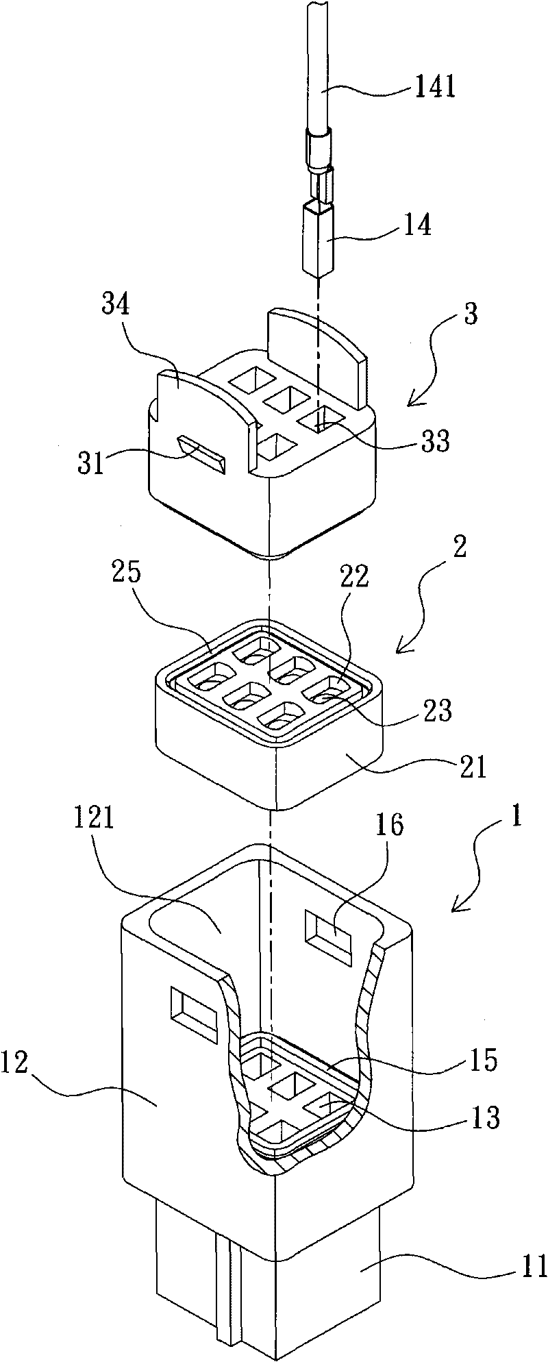
[0051] Such as Figure 4 to Figure 6b As shown, the second embodiment of the electrical connector of the present invention is composed of a housing 1, a sealing ring 2, and a grid member 3.
[0052] Wherein, the structure of the casing 1 and the grille member 3 are the same as the first embodiment, and will not be repeated here.
[0053] The sealing ring 2 is different from the first embodiment in that at least one outer rib 27 is protruded from the circumferential surface of the plug 21 of the sealing ring 2, such as Figure 4 As shown, it is better to have an outer rib 27 protruding from the circumferential surface of the connector 21 adjacent to the top and bottom ends. The first and second circumferential positioning grooves 24, 25 have a guiding inclined surface 28 formed radially inward from the outer side of the annular opening, which facilitates the guiding of the positioning flanges 15, 32 into the corresponding first and second circumferential positioning grooves. 24 and 25, and by the pushing action of each flange on the circumferential positioning groove, the two outer ribs adjacent to the circumferential inner wall of the accommodating space are squeezed and deformed, so that the upper and lower parts of the outer wall of the connector 21 are respectively Close to the circumferential inner wall of the accommodating space 121, thereby forming a double circumferential sealing effect.
[0054] See Figure 6a When assembling the second embodiment of the present invention, the sealing ring 2 is first inserted into the accommodating space 121 at the bottom of the housing 1, so that the first circumferential positioning groove 24 on the top surface of the plug 21 is inserted into the accommodating space. The first positioning flange 15 on the inner wall of the top of the space 121. Then, the grid member 3 is inserted into the accommodating space 121 at the bottom of the casing 1 so that the second positioning flange 32 on the top surface is inserted into the second circumferential positioning groove 25 on the bottom surface of the plug 21. At this time, because the protrusion 31 has not been snapped into the buckle groove 16, the upper and lower outer ribs 27 of the outer wall of the peripheral surface of the plug member 21 abut the inner peripheral wall of the accommodating space 121. See Figure 6b , Finally continue to apply force to the grille member 3, so that the protrusion 31 is buckled in the buckle groove 16, and the plug member 21 is subjected to the force of the grille member 3, so that the flanges 15, 32 are aligned in the circumferential direction. The positioning grooves 24 and 25 are pushed to squeeze and deform the outer ribs 27 adjacent to the circumferential inner wall of the accommodating space 121, so that the upper and lower portions of the outer wall of the plug 21 are respectively close to the circumferential inner wall of the accommodating space 121, In turn, a double circumferential sealing effect is formed.

PUM

no PUM

Description & Claims & Application Information

We can also present the details of the Description, Claims and Application information to help users get a comprehensive understanding of the technical details of the patent, such as background art, summary of invention, brief description of drawings, description of embodiments, and other original content. On the other hand, users can also determine the specific scope of protection of the technology through the list of claims; as well as understand the changes in the life cycle of the technology with the presentation of the patent timeline. Login to view more.
Why Eureka
Try Eureka