
Aerial photograph central type shutter mechanism
An aerial photography and shutter technology, applied in the field of aerial cameras, can solve the problems of large number of blades, complex mechanism, low speed and efficiency, etc., to achieve the effect of improving image quality, avoiding impact phenomenon, and avoiding mechanical damage.
- Summary
- Abstract
- Description
- Claims
- Application Information
AI Technical Summary
Problems solved by technology
Method used
Image

Examples
Embodiment Construction
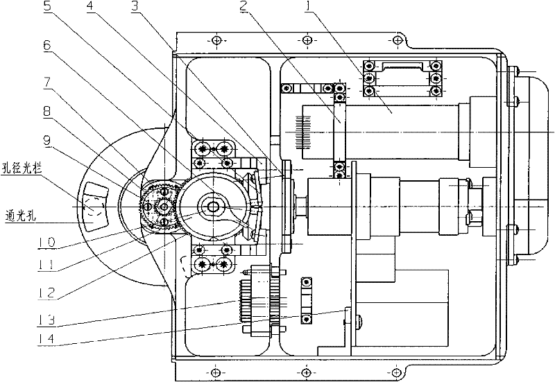
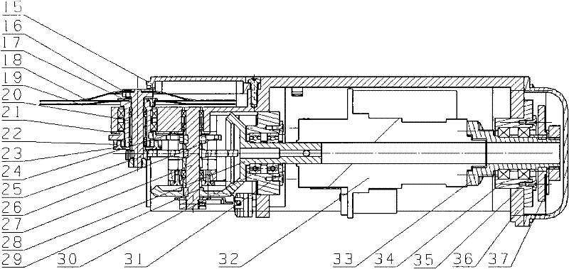
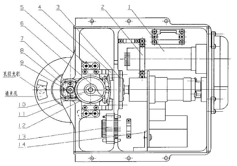
[0019] Image aerial photography center type shutter mechanism of the present invention such as figure 1 , figure 2 As shown in Fig. 3, blade A 18 and blade B 19 are made of carbon fiber (M40) respectively, which have good rigidity. Under the conditions of humidity of 40 to 70% RH and working temperature of -50°C to +50°C, Good dimensional stability is maintained; fixed on the A rotating shaft 25 and the B rotating shaft 20 through the A pressing plate 16 and the B pressing plate 17 respectively. The A rotating shaft 25 is installed on the B rotating shaft 20 through precision bearings, and the two rotating shafts are concentric. The other ends of the two rotating shafts are respectively equipped with the A gear 7 and the B gear 8, which mesh with the C gear 12 and the D gear 26 on the C rotating shaft 27 respectively. The transmission ratios of the two pairs of gear pairs are 1:1 and 4:1 respectively. The A bevel gear 11 on the C rotating shaft 27 is engaged with the B beve...
PUM
 Abstract
Description
Claims
Application Information