
Contact workpiece detection mechanism of pneumatic and hydraulic punching machine

A technology for workpiece detection and stamping machines, which is applied in the direction of presses, manufacturing tools, mechanical equipment, etc., can solve the problems of small workpiece size, personal injury, punch down pressure, etc., and achieve the effect of improving operation efficiency

Inactive Publication Date: 2010-06-16
KUNSHAN SMART MACHINERY
View PDF10 Cites 0 Cited by
  • Summary
  • Abstract
  • Description
  • Claims
  • Application Information

AI Technical Summary

Problems solved by technology

However, some workpieces are small in size, and the operator needs to hold the workpiece with his hands and punch it on the console. The position of the hand and the punch is relatively close. Press the foot switch, the punch must be pressed down, causing personal injury
Analysis of the cause: the operator accidentally put his hand under the punch, and accidentally stepped on the foot switch, and the punch was pressed down, causing personal injury

Method used


Image

  • Contact workpiece detection mechanism of pneumatic and hydraulic punching machine
  • Contact workpiece detection mechanism of pneumatic and hydraulic punching machine
  • Contact workpiece detection mechanism of pneumatic and hydraulic punching machine

Examples


Embodiment Construction

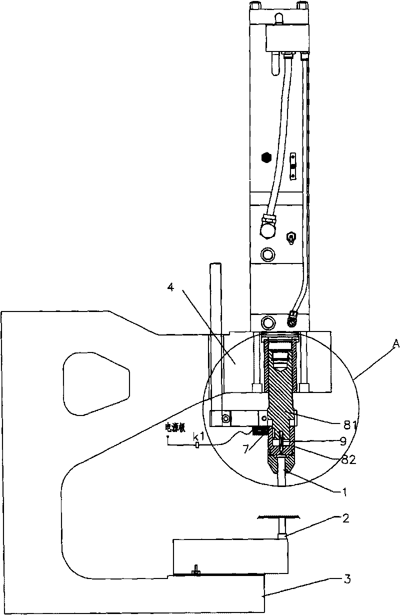
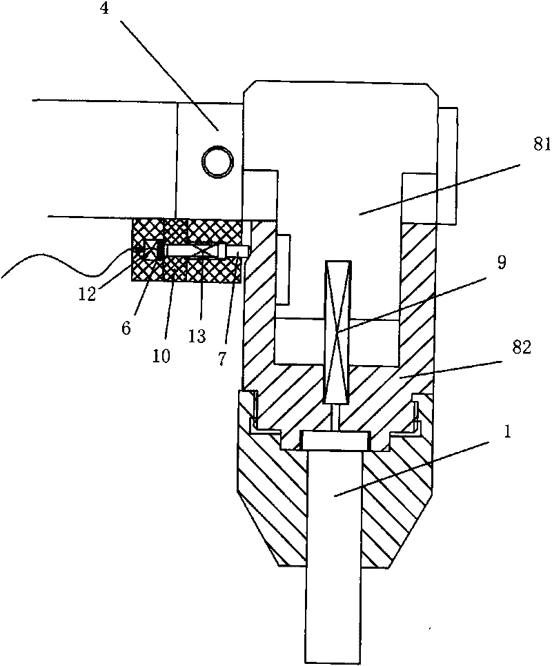
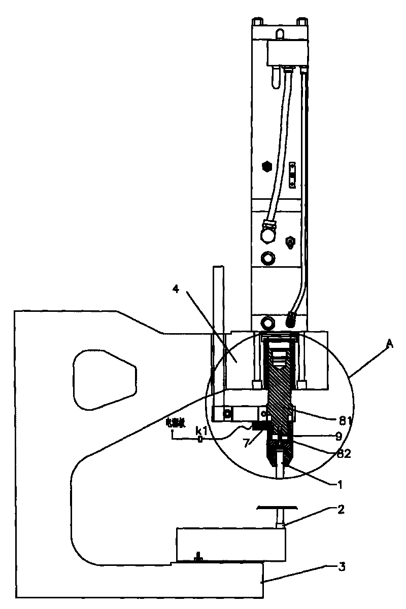
[0009] A pneumatic hydraulic stamping machine contact workpiece detection mechanism, installed between the upper mold 1 and the lower mold 2, the upper mold 1 is fixed on the stamping spindle, the lower mold 2 is fixed on the punching machine console 3, the detection mechanism includes a power supply Pole, start detection relay K1, conductive sheet 6, thimble 7, stamping spindle and ground electrode constitute a start detection circuit, the power supply pole, start detection relay K1 and conductive sheet 6 are connected in series in sequence, and the punching spindle is composed of upper spindle 81 and lower Main shaft 82, the lower end of the upper main shaft 81 is sleeved on the upper end of the lower main shaft 82, and a compression spring 9 is arranged between the upper main shaft 81 and the lower main shaft 82, the upper main shaft is connected to the ground electrode and the lower end of the lower main shaft 82 is fixed In the upper mold 1, one end of the thimble 7 is lim...


PUM


Abstract

The invention discloses a contact workpiece detection mechanism of a pneumatic and hydraulic punching machine. The contact workpiece detection mechanism is arranged between an upper mould and a lower mould, wherein the upper mould is fixed on a main punching main shaft; the lower mould is fixed on an operating console of the punching machine; the detection mechanism comprises a starting detection circuit consisting of a power supply electrode, a starting detection relay, a conducting strip, a thimble, the main punching shaft and an earth electrode; the power supply electrode, the starting detection relay and the conducting strip are serially connected in sequence; the main punching shaft consists of an upper main shaft and a lower main shaft; the lower end part of the upper main shaft is sleeved at the upper end part of the lower main shaft; a compression spring is arranged between the upper main shaft and the lower main shaft; the upper main shaft is connected with the earth electrode and the lower end of the lower main shaft is fixed on the upper mould; the other end of the thimble is contacted with the conducting strip while one end of the thimble is limited at the side of the lower main shaft through a fixed spring; a concave part is arranged at the side part of the lower main shaft; the other end of the thimble is separated from the conducting strip while one end of the thimble is limited at the concave part of the lower main shaft; and the contact workpiece detection mechanism of the pneumatics and hydraulic punching machine can automatically judge whether a punching head is in contact with the workpiece or not.

Description

technical field [0001] The invention belongs to a safety detection device for stamping processing equipment, in particular to a detection mechanism that can automatically detect that a stamping machine touches a workpiece during the stamping process using a gas-hydraulic hybrid power. Background technique [0002] The upper mold 1 on the stamping machine is fixed on the stamping spindle (such as figure 1 As shown), the stamping spindle is started by the stamping cylinder for stamping, and the workpiece 100 is placed on the lower die 2 on the press console 3. During the stamping process, the operator needs to operate the workpiece by hand. When some workpieces are very large, the operator can It is safer to operate by holding the side of the workpiece and away from the stamping direction of the stamping cylinder. However, some workpieces are small in size, and the operator needs to hold the workpiece with his hands and punch it on the console. The position of the hand and th...

Claims


Application Information

Patent Timeline
Patent Type & Authority Applications(China)
IPC IPC(8): B30B15/16F16P3/12
Inventor 夏扣林
Owner KUNSHAN SMART MACHINERY
Learn More