Plane type key structure

A flat, button technology, applied in the direction of telephone structure, electrical components, electrical switches, etc., can solve the problems of being linked, poor pressing feel, etc.

Inactive Publication Date: 2010-06-16
INVENTEC CORP
View PDF0 Cites 8 Cited by
  • Summary
  • Abstract
  • Description
  • Claims
  • Application Information

AI Technical Summary

Problems solved by technology

If the buttons are placed too close to each other, when one button is pressed, another adjacent button will often be pulled, resulting in a bad pressing feel or a problem of being linked.

Method used


Image

  • Plane type key structure
  • Plane type key structure
  • Plane type key structure

Examples


no. 1 example

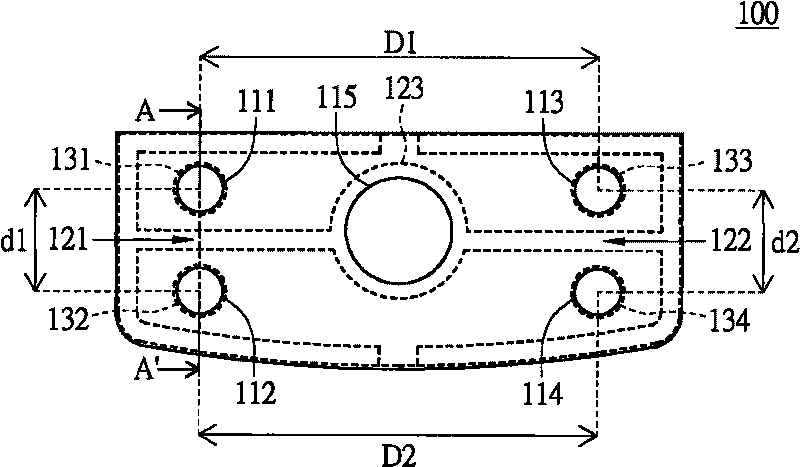
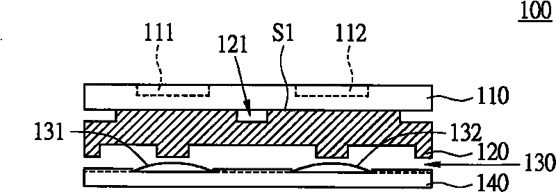
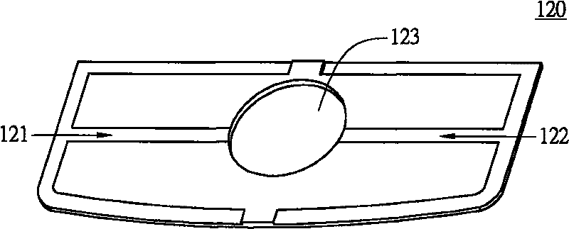
[0014] Please also refer to Figure 1A as well as Figure 1B , which respectively show a top view of a planar key structure according to the first embodiment of the present invention and Figure 1A A cross-sectional view of the mid-plane key structure along the section line AA'. The planar key structure 100 is used in an electronic device (not shown in the figure), such as a mobile phone, and the electronic device includes a circuit board 140 , such as a flexible printed circuit (FPC). The planar key structure 100 includes a planar key sheet 110 , an elastic material layer 120 and a metal elastic layer 130 . The planar key sheet 110 is, for example, a planar plastic sheet and a plurality of key patterns are printed on the planar plastic, including first keys 111 and second keys 112 arranged adjacently, and third keys 113 and fourth keys arranged adjacently. Button 114, such as Figure 1A shown. It should be noted that the distance d1 between the first button 111 and the seco...

no. 2 example

[0025] Please also refer to Figure 2A as well as Figure 2B , which respectively show a top view of a planar button structure according to the second embodiment of the present invention and Figure 2A The cross-sectional view of the mid-plane key structure along the BB’ section line. The planar key structure 200 is used in an electronic device (not shown in the figure), such as a mobile phone, and the electronic device includes a circuit board 250, such as a flexible circuit board. The planar key structure 200 includes a planar key sheet 210 , an elastic material layer 220 , a metal elastic layer 230 , and a first bump 241 and a second bump 242 .

[0026]The planar key sheet 210 is, for example, a planar plastic sheet and a plurality of key patterns are printed on the planar plastic, including a first key 211 and a second key 212 arranged adjacently, a third key 213 and a fourth key arranged adjacently 214 and the multidirectional key 215 located in the middle of the keys ...


PUM


Abstract

The invention relates to a plane type key structure used in an electronic device comprising a circuit board. The plane type key structure comprises a plane key board, an elastic material layer and a metal elastic piece layer, wherein the plane key board comprises a first key and a second key which are adjacently arranged; the elastic material layer is connected below the plane key board, and the upper surface of the elastic material layer connected with the plane key board is provided with a first groove which is arranged between the first key and the second key and used for obstructing the press linkage effect of the first key and the second key; the metal elastic piece layer is connected below the elastic material layer and arranged on the circuit board; and a first metal elastic piece and a second metal elastic piece which respectively correspond to the first key and the second key are arranged on the metal elastic piece layer.

Description

technical field [0001] The present invention relates to a planar key structure, and in particular to a planar key structure in which an elastic material layer is located between two adjacent keys and has grooves or bumps. Background technique [0002] The basic structure of today's mobile phone buttons usually includes an exterior button, a rubber sheet and a metal dome layer. If a plurality of exterior buttons are all presented by a flat plastic sheet, that is, the graphic of each button is printed on the flat plastic, which is a so-called flat button, and each button graphic corresponds to the metal dome of the metal dome layer. If the buttons are placed too close to each other, in the process of pressing one button, another adjacent button will often be pulled, resulting in a bad pressing feel or a problem of being linked. Contents of the invention [0003] The object of the present invention is to provide a planar button structure, the elastic material layer of which ...

Claims


Application Information

Patent Timeline
IPC IPC(8): H01H13/704H01H13/7057H04M1/23
Inventor 张静如
Owner INVENTEC CORP
Why Eureka
Try Eureka