High-speed aircraft capable of taking off and landing vertically as well as control method of high-speed aircraft

A high-speed aircraft, vertical take-off and landing technology, applied in the field of aviation aircraft, can solve the problems of low vertical take-off and landing efficiency, high cost, and worse, to improve safety factor and practicability, improve take-off and landing safety, and reduce aerodynamic interference Effect

Inactive Publication Date: 2016-08-24
邓阳平
View PDF6 Cites 13 Cited by
  • Summary
  • Abstract
  • Description
  • Claims
  • Application Information

AI Technical Summary

Problems solved by technology

It is a typical American V-22 "Osprey", but due to the poor dynamic stability of this type of aircraft in the transitional flight state and the strong aerodynamic interference between the rotor and the wing, their application prospects have been questioned by many people
Multiple V-22 Ospreys crashed because of the problem, making it even worse
However, vertical take-off and landing aircraft such as the "Harrier" and the American F-35B use their powerful engine thrust and thrust steering control technology to realize the transition between vertical take-off and landing and flat flight, but they have high requirements on the engine. There are also disadvantages such as low vertical take-off and landing efficiency, high control complexity, and high cost. It is only suitable for military fighter jets and is not suitable for development into light and small aircraft and unmanned aerial vehicles.

Method used


Image

  • High-speed aircraft capable of taking off and landing vertically as well as control method of high-speed aircraft
  • High-speed aircraft capable of taking off and landing vertically as well as control method of high-speed aircraft
  • High-speed aircraft capable of taking off and landing vertically as well as control method of high-speed aircraft

Examples


Embodiment 1

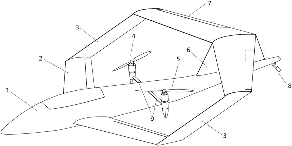
[0052] Example 1 as figure 1 and figure 2 As shown, the design scheme includes the fuselage, vertical tail and power system; the maximum diameter of the fuselage section is 0.2 meters, and it is a slender body with a length of 1.8m. The interior of the fuselage contains mission loads, power batteries and flight control equipment.

[0053] The vertical tail is installed at the rear of the fuselage, mainly for heading stability; the area of ​​the vertical tail is 0.06m 2 , the wing root chord length is 0.43m, the wing tip chord length is 0.27m, the height is 0.17m, the leading edge sweep angle is 33°, the twist angle is 0°, and the rudder is installed at the tail of the vertical tail.

[0054] The wing part of the design scheme adopts a connecting wing, and the connecting wing is composed of a front wing, a rear wing and a flat plate structure. The front wing has a sweep angle, and the front wing is installed symmetrically under the two sides of the front part of the fuselag...

Embodiment 2

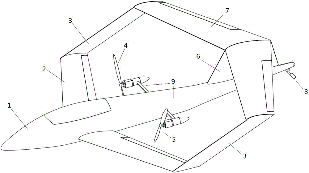
[0063] Example 2 as image 3 and Figure 4 As shown, the difference between this design and Embodiment 1 is that the other end of the flat plate structure is connected to the 50% span of the front wing.

Embodiment 3

[0064] Example 3 as Figure 5 and Figure 6 As shown, the connecting wing structure of this design is different from that of Example 1. There is no flat structural member, but the two ends of the rear wing are directly connected to the front wing tip, and the rear wing has a larger dihedral angle.


PUM


Abstract

The invention provides a high-speed aircraft capable of taking off and landing vertically as well as a control method of the high-speed aircraft. The high-speed aircraft adopts wings in the form of a joined wing, a middle propeller of a fuselage is mounted in the middle of front and back wings of the joined wing, compared with aircrafts such as V22 Osprey aircrafts and the like, the high-speed aircraft has the advantages that the propeller is not mounted or fixed on the wings, downward and backward wash flows of the propeller cannot sweep the wings in the flying process, so that aerodynamic interference between the wash flows of the propeller and the wings of the aircraft in the whole flying process is greatly reduced, smooth transition from vertical taking off and landing to high-speed forward flying of the aircraft can be realized, the safety coefficient of the aircraft is increased, and the practicability of the aircraft is improved; besides, the middle propeller is surrounded in the middle of the joined wing, and the propeller can be effectively prevented from being collided by ground objects at vertical taking off and landing stages, so that the taking off and landing safety is improved.

Description

technical field [0001] The invention relates to the technical field of aviation aircraft, in particular to a high-speed aircraft capable of vertical take-off and landing and a control method thereof. Background technique [0002] Since the take-off and landing of fixed-wing aircraft requires a certain sliding distance to be realized, a relatively open take-off and landing field and a long runway are required. The construction of landing sites is expensive, time-consuming, and easily destroyed during wartime. Therefore, people hope to have a kind of aviation vehicle that can take off and land in narrow space always. With the birth of helicopters, this demand of people has been met to a certain extent. However, due to the asymmetry of the rotor airflow in the forward flight environment of the helicopter, the maximum forward flight speed of the helicopter is affected by the compressibility of the forward blades and the airflow separation of the backward blades. The maximum cr...

Claims


Application Information

Patent Timeline
Patent Type & Authority Applications(China)
IPC IPC(8): B64C27/52
CPCB64C27/52
Inventor 邓阳平郜奥林田力高红岗
Owner 邓阳平
Why Eureka
Try Eureka