Binding machine

A binding machine and binding hole technology, which is applied in the field of binding machines, can solve problems such as dislocation of joints and large thickness dimensions, and achieve the effects of easy binding, restraining the increase of thickness dimensions, and avoiding excessive thickening of the thickness

Active Publication Date: 2010-06-23
KOKUYO CO LTD
View PDF1 Cites 5 Cited by
  • Summary
  • Abstract
  • Description
  • Claims
  • Application Information

AI Technical Summary

Problems solved by technology

As a result, when the joint parts of the bound sheets are caught by other articles or fingers, the joint parts may be dislocated or the joints may be released due to the hooking of the cut pieces.
In addition, when the sheets bound in this way are stacked, only the joined portion becomes thicker than other portions.
[0006] And especially such defect, when the number of sheets to be bound increases or when joining thicker sheets, etc., that is, when the total size of the thickness of a plurality of sheets increases, it will particularly remarkably occur.
According to such a situation, the present situation is that the thickness dimension of the sheets bound by the conventional binding machine of this structure will naturally become larger.

Method used


Image

  • Binding machine
  • Binding machine
  • Binding machine

Examples


no. 1 approach

[0059] A first embodiment of the invention will be described below with reference to the drawings.

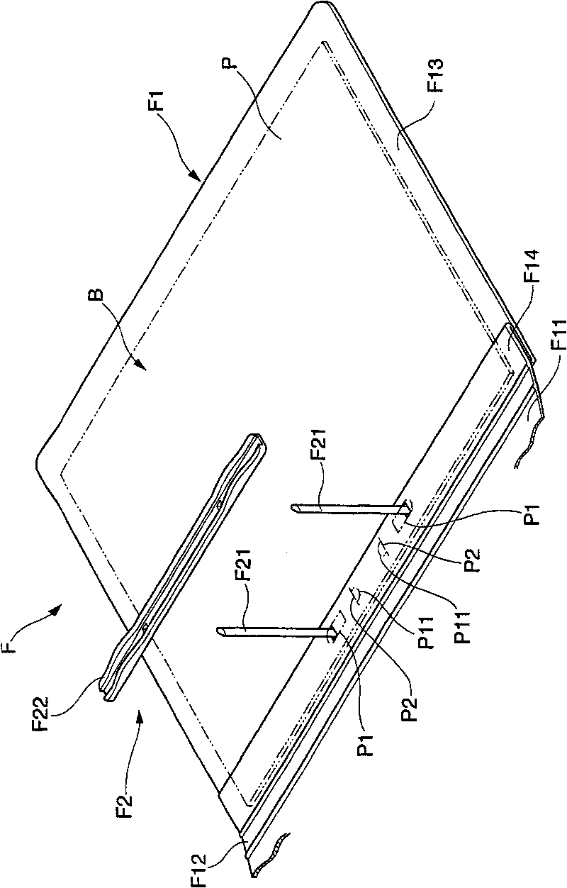
[0060] The binding machine 1 that this embodiment relates to, as Figure 1 to Figure 3 As shown, it can be suitably applied to the folder system of the booklet B in which one or more volumes are bound by the folder F. FIG.

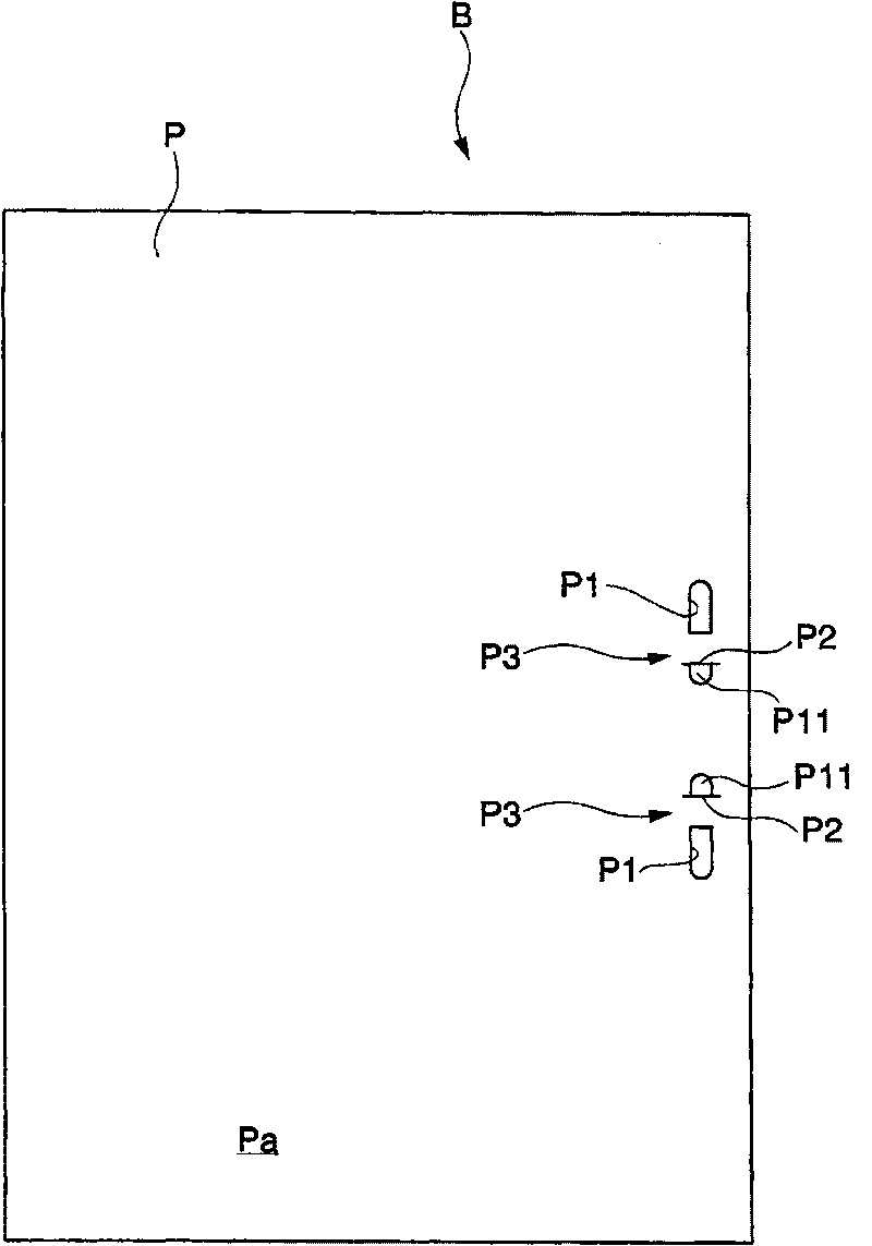
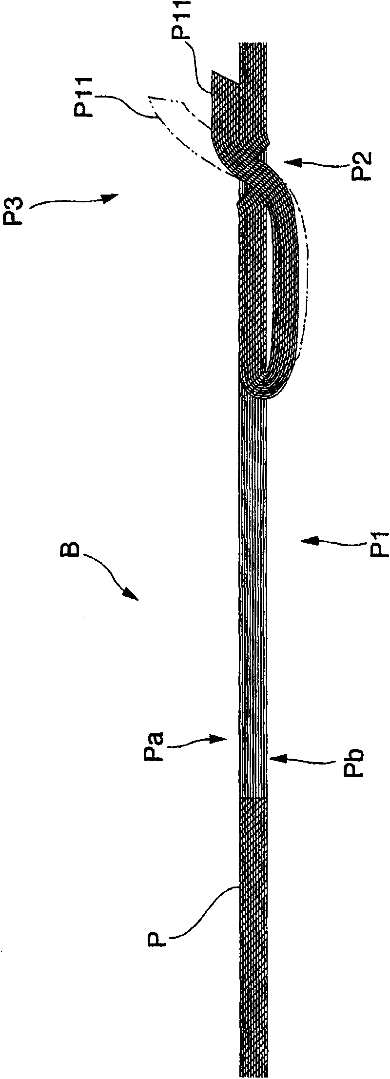
[0061] Such as figure 1 and figure 2 As shown, the booklet B is formed by bundling a plurality of sheets made of homogeneous materials, for example, a plurality of sheets P, and these sheets P are joined to each other at two joining portions P3 set on the binding side. Each joint portion P3 is composed of: a binding hole P1 formed on each paper P by a punching blade 92 penetrating from the side Pa of the paper P; a pull-up cutting hole P2 adjacent to the binding hole P1 and Formed on each of the above-mentioned paper sheets P; the cut-out piece P11 is cut from the above-mentioned binding hole P1 toward the reverse side Pb of the paper sheet P. Then, by...

no. 2 approach

[0093] Next, refer to Figure 17 to Figure 33 The binding machine A1 that is directly used for implementing such a file system will be described.

[0094] This bookbinding machine A1 is a device for joining a plurality of sheets of paper P as sheets to produce the above-mentioned booklet B, such as Figure 17 As shown, it is provided with: a stage A2 placed on the table; a main body A3 fixedly arranged on the stage A2; ユニツト), which can be lifted and accommodated in the main body A3 and equipped with a punching blade A92 and a cutting blade A91 described later; a paper holder A8 (paper base, paper tape reel seat), which ends the perforation at the blade changing unit A4 When moving up, it is used to lift the above-mentioned bound paper P; the operating handle A5 is installed on the above-mentioned main body A3 so as to be rotatable up and down in order to make the paper holder A8 and the blade changing unit A4 move.

[0095] Such as Figure 17 , Figure 21 and Figure 22 ...


PUM


Abstract

The invention provides a binding machine, which can effectively maintain the joint state of a jointed joint part when a plurality of sheet pieces are bound. The binding machine (1), by using cutting pieces (P11) obtained by cutting the overlapped paper (P) by means of a objective table (2), a cutting blade (910 and a punching blade (92), mutually joint the paper (P) for binding. The binding machine is characterized in that the binding machine has a compressing mechanism, which can make the jointed joint portion (P3) of the paper (P) compressed and deformed in the thickness direction. In this way, because the jointed joint portion is compressed, the joint portion (P3) can be effectively prevented from hanging other articles or fingers due to the swelling of the cutting pieces (P11), the joint state of the joint portion (P3) can be steadily maintained, and the thickness of the joint portion (P3) can be reduced.

Description

technical field [0001] The present invention relates to a binding machine capable of joining a plurality of sheets (sheets, sheet-like objects). Background technique [0002] Conventionally, other devices called so-called staplers (staplers) have been used as devices capable of binding a plurality of sheets of paper (paper, forms), etc., using metal staples to bind a plurality of sheets. , it is proposed that there is a binding machine capable of binding a plurality of sheets by only utilizing the structure of the sheet itself. [0003] Specifically, various binding machines have been proposed that can engage and join the sheets by cutting (cutting り ここ, cutting out) a part of a plurality of sheets and cutting them up (cut-up sheet) ( For example, refer to Patent Document 1). Such a device has the advantage of effectively saving the work of dismantling when the plurality of sheets are discarded because the binding can be completed with only a plurality of sheets. [0004]...

Claims


Application Information

Patent Timeline
Patent Type & Authority Applications(China)
IPC IPC(8): B42B4/00B65H37/04
Inventor 青井宏和
Owner KOKUYO CO LTD
Why Eureka
Try Eureka