

Flaw detector for wire rope
A flaw detection device and steel cable technology, applied in the direction of material magnetic variables, etc., can solve problems such as large pushing force, influence of leakage magnetic flux detection value, and difficulty in setting, and achieve the effects of suppressing vibration, suppressing output changes, and improving reliability
- Summary
- Abstract
- Description
- Claims
- Application Information
AI Technical Summary
Problems solved by technology
Method used
Image

Examples
Embodiment Construction
[0026] Hereinafter, the best mode of the flaw detection device for carrying out the steel cable of the present invention will be described with reference to the drawings.
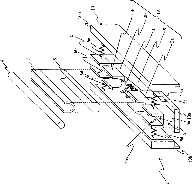
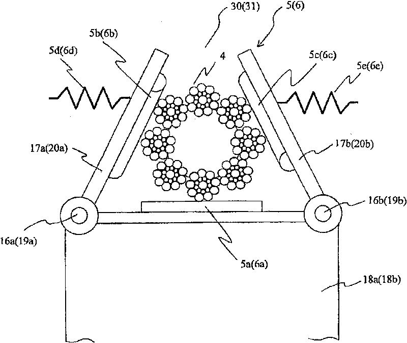
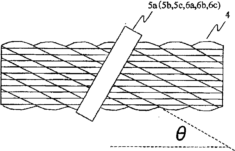
[0027] figure 1 It is an exploded perspective view showing the structure of the flaw detection device for a steel cable according to the first embodiment of the present invention, figure 2 It is a front view showing the positioning mechanism included in the first embodiment of the present invention, image 3 It is a figure which shows the positional relationship of a rotating body and a wire rope in the flaw detection inspection of a wire rope implemented by 1st Embodiment of this invention.
[0028] Such as figure 1 As shown, the steel cable flaw detection device 1 according to the first embodiment of the present invention has: a housing 10 formed by a bottom plate 10a and a pair of side plates 10b, 10c; and a magnetic flux detection member 1A arranged in the center of the housing 10 A pair of position...
PUM
 Abstract
Description
Claims
Application Information