Driving device of luminous element

A technology for driving devices and light-emitting elements, which is applied to lighting devices, light sources, electric light sources, etc., can solve the problems of uneven brightness of display panels and different driving currents of driving circuits.

Active Publication Date: 2010-07-14
AU OPTRONICS CORP
View PDF3 Cites 10 Cited by
  • Summary
  • Abstract
  • Description
  • Claims
  • Application Information

AI Technical Summary

Problems solved by technology

As a result, the driving current generated by the driving circuit is different in size, so that the brightness of each pixel has a slight difference, resulting in uneven brightness on the display panel.

Method used


Image

  • Driving device of luminous element
  • Driving device of luminous element
  • Driving device of luminous element

Examples


Embodiment Construction

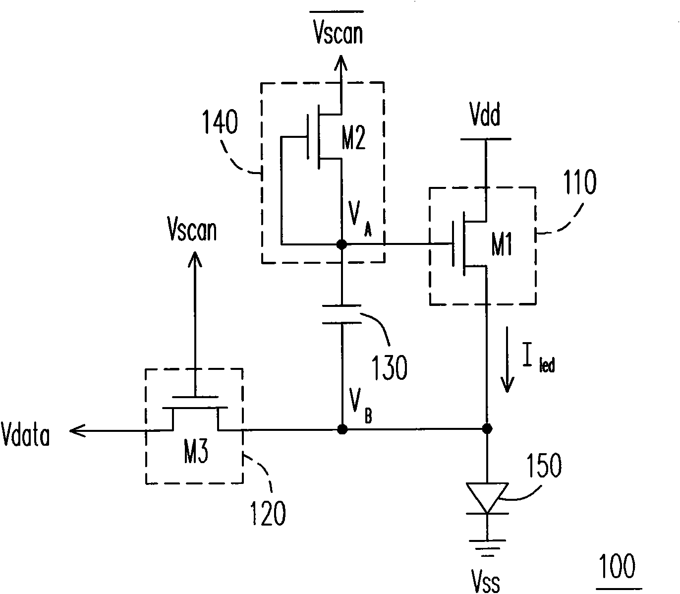
[0042] The following describes the embodiments of the present invention, wherein the pixel driving circuit in the display panel is used as the implementation mode, so that those skilled in the art can better understand the spirit of the present invention. Please refer to figure 1 , figure 1 It is an equivalent circuit diagram illustrating the driving device 100 of the light emitting element 150 according to the first embodiment of the present invention. In this embodiment, the light emitting element 150 and the driving device 100 are pixel circuits in the display panel. The driving device 100 includes a driving circuit 110 , a switch 120 , a capacitor 130 and a compensation circuit 140 . The driving circuit 110 has a control terminal and a driving terminal, and the driving terminal is connected to one terminal of the light emitting element 150 , and the other terminal of the light emitting element 150 receives the ground voltage Vss. The driving circuit 110 determines the d...


PUM


Abstract

The invention discloses a driving device of a luminous element, comprising a driving circuit, a switch, a capacitor and a compensation circuit. The driving circuit is provided with a control end and a driving end which is connected to a luminous element. The driving circuit decides a driving current according to the voltage of the control end. A first end of the switch receives a data voltage; a second end of the switch is connected to the luminous element; and a control end of the switch receives a scanning voltage. A first end of the capacitor is connected to the control end of the driving circuit; and a second end of the capacitor is connected to the second end of the switch. The output end of the compensation circuit is connected to the first end of the capacitor; and the compensation circuit provides a resetting voltage to the first end of the capacitor during the conduction of the switch.

Description

technical field [0001] The present invention relates to a driving device for a light-emitting element, and in particular to a driving device for a light-emitting element used in a pixel circuit. Background technique [0002] With the advancement of electronic technology, people have higher and higher requirements for visual services provided by consumer electronic products. Whether it is on a TV, personal computer, mobile phone, etc., the quality of the display is very particular. The development of flat-panel display technology is also constantly innovating. Among them, organic light-emitting diode (Organic Light-Emitting Diode, OLED), also known as organic electroluminescence (OEL), has characteristics that are difficult to achieve with other flat-panel display technologies, including power saving, Ultra-thin thickness, light weight, self-illumination, no viewing angle limitation, fast response, high photoelectric efficiency, no need for backlight structure and color filt...

Claims


Application Information

Patent Timeline
Patent Type & Authority Applications(China)
IPC IPC(8): H05B37/02
Inventor 蔡宗廷
Owner AU OPTRONICS CORP
Why Eureka
Try Eureka