Back light device and its brightness control circuit control method

A technology of brightness control and backlight device, which is applied in the direction of lighting device, lamp circuit layout, light source, etc., and can solve problems such as differences in operating current, different luminous brightness of light-emitting modules, and uneven brightness of display screens.

Inactive Publication Date: 2008-11-26
CHUNGHWA PICTURE TUBES LTD
View PDF0 Cites 13 Cited by
  • Summary
  • Abstract
  • Description
  • Claims
  • Application Information

AI Technical Summary

Problems solved by technology

As a result, in the case of inputting a fixed operating voltage, each light-emitting module will have a different operating current due to the different total cross-voltage values ​​of th

Method used


Image

  • Back light device and its brightness control circuit control method
  • Back light device and its brightness control circuit control method
  • Back light device and its brightness control circuit control method

Examples


Embodiment Construction

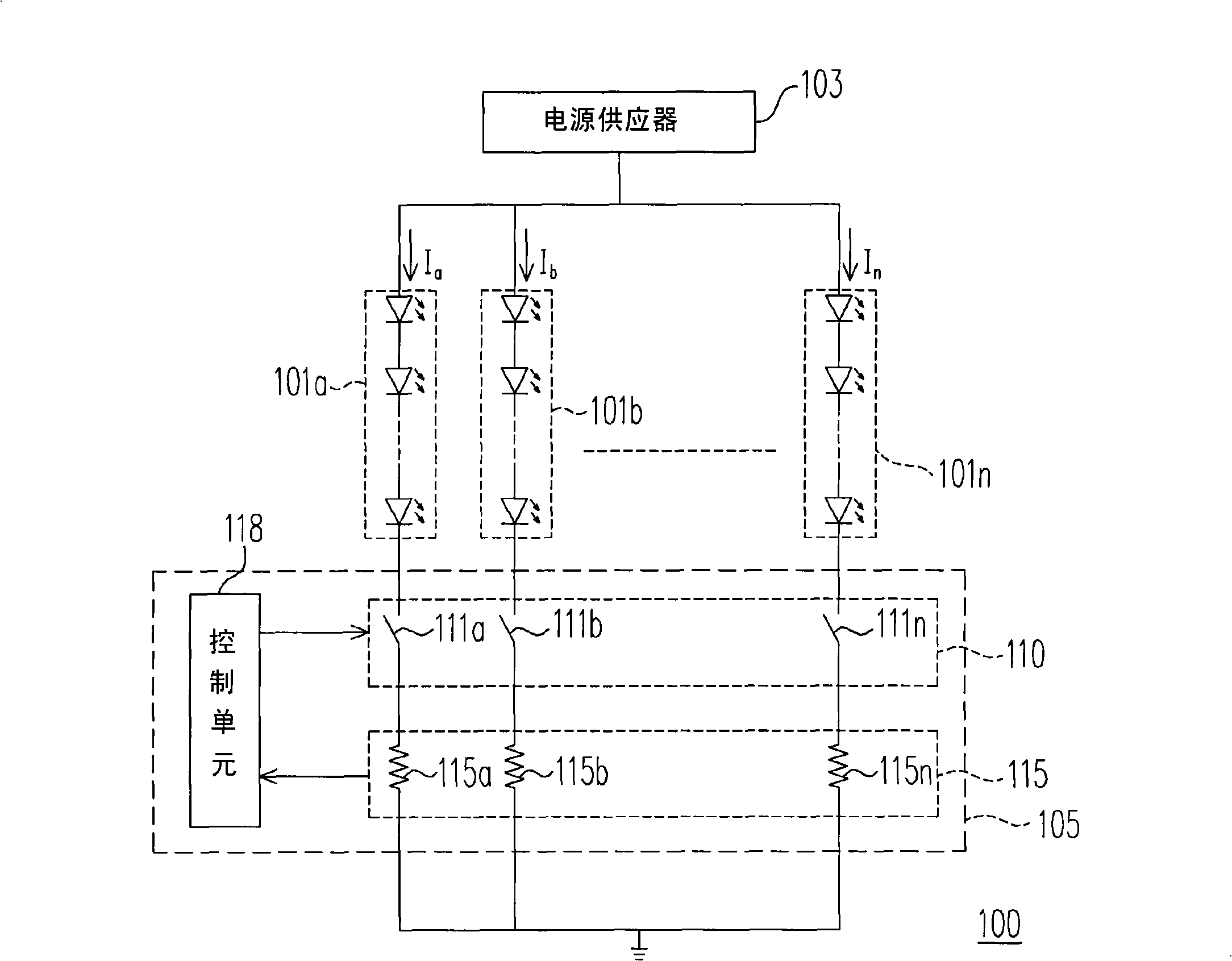
[0018] figure 1 It shows a backlight device according to a preferred embodiment of the present invention. Please refer to figure 1 The backlight device 100 includes a power supply 103 , a brightness control circuit 105 and a plurality of light emitting modules ( 101 a - 101 n ). Wherein, the power supply 103 provides the power required for the operation of each light emitting module (101a-101n), and the brightness control circuit 105 is suitable for synchronously controlling the brightness of multiple light emitting modules (101a-101n).

[0019] The brightness control circuit 105 includes a detection unit 115 , a control unit 118 and a current adjustment unit 110 . Wherein, the detection unit 115 also includes a plurality of resistors (115a-115n), which are respectively coupled to the corresponding light-emitting modules (101a-101n) to detect the working current (Ia-In ) and generate a plurality of detection signals to be sent to the control unit 118. In addition, the curr...


PUM


Abstract

The invention discloses an intensity circuit, which comprises a detecting unit, a control unit and a current regulating unit, wherein, the detecting unit is used for detecting the working current size of each luminescence module and producing a plurality of detecting signals to the control unit; the control unit can produce a plurality of control signals according to the detecting signals and deliver the control signals to the current regulating unit; the current regulating unit can adjust the working current size of each luminescence module.

Description

technical field [0001] The present invention relates to a backlight device and its brightness control circuit, and in particular to a control method of the backlight device and its brightness control circuit. Background technique [0002] Because light emitting diodes (light emitting diodes) have the characteristics of small size, power saving and long service life, light emitting diodes are widely used in various information devices such as mobile phones, cameras, and liquid crystal displays. [0003] In the case of liquid crystal displays, light emitting diodes can be used as its backlight. When a liquid crystal display uses light-emitting diodes as a backlight source, a large number of light-emitting diodes must be used so that the brightness of the display screen can meet user requirements. In addition, since the liquid crystal display uses a large number of light-emitting diodes, the driving current of the light-emitting diodes increases and the number of driving circu...

Claims


Application Information

Patent Timeline
IPC IPC(8): G09G3/20G09G3/22G09G3/36H05B37/02
Inventor 赵翰楀陈弼先林信彰
Owner CHUNGHWA PICTURE TUBES LTD
Why Eureka
Try Eureka