Light guide plate, optical diaphragm, backlight module, array substrate and liquid crystal module

An optical film and array substrate technology, applied in optics, optical elements, nonlinear optics, etc., can solve the problems of uneven viewing angle characteristics of liquid crystal, gray scale reversal color, shift and other problems, so as to overcome the viewing angle dependence problem, prevent the light leak effect

Inactive Publication Date: 2013-06-12
BOE TECH GRP CO LTD
View PDF4 Cites 14 Cited by
  • Summary
  • Abstract
  • Description
  • Claims
  • Application Information

AI Technical Summary

Problems solved by technology

In addition, theoretically, when the thin film transistor is energized, such as figure 2 As shown, the light passing through the liquid crystal molecules 5 perpendicular to the array substrate 1 cannot pass through the polarizer 4 on the side of the color filter substrate 2, but in fact, if the user sees the liquid crystal molecules 5 within a specific angle range The long axis, that is, the light transmittance at this viewing angle increases instead, so that the low-gray-scale picture may look brighter than the high-gray-scale picture, which is the inherent gray-scale reversal phenomenon of TFT-LCD
[0004] Due to the uneven viewing angle characteristics of liquid crystals, there are often more serious gray scale reversals or color shifts in viewing angles other than the normal line of the display panel.
In the prior art, wide viewing angle display mode or compensation film for viewing angle compensation are often used to improve the viewing angle, but these two methods cannot completely solve the viewing angle problem of TFT-LCD.
The technical problem to be solved by the present invention is how to realize a backlight source with a high concentration degree, so as to completely solve the visual dependence problem of TFT-LCD

Method used


Image

  • Light guide plate, optical diaphragm, backlight module, array substrate and liquid crystal module
  • Light guide plate, optical diaphragm, backlight module, array substrate and liquid crystal module
  • Light guide plate, optical diaphragm, backlight module, array substrate and liquid crystal module

Examples


Embodiment 1

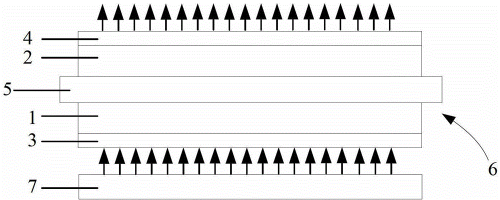
[0035] combine Figure 5-Figure 7 As shown, in order to achieve the purpose of parallel incident of light rays into the array substrate along the same angle, a light guide plate is provided in this embodiment, and a reflective layer 10 and a light concentrating layer 11 are formed on one surface of the light guide plate 9, specifically, by The reflective layer 10 and the light concentrating layer 11 are respectively formed on one surface of the light guide plate 9 by processes such as coating, deposition, and sputtering. Wherein, the reflective layer 10 is positioned under the light concentrating layer 11, and a plurality of small holes 12 are arranged on the reflective layer 10, so as to form a point light source at the position of each small hole 12, and the light concentrating layer 11 is opposite to each point light source. The rays are converged so that the outgoing rays are parallel rays traveling in the same direction, such as Figure 8 shown. Generally, the light is ...

Embodiment 2

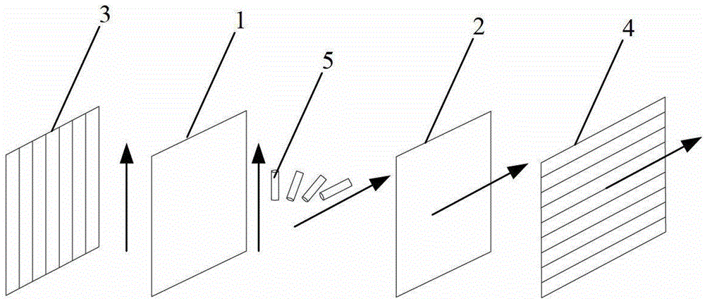
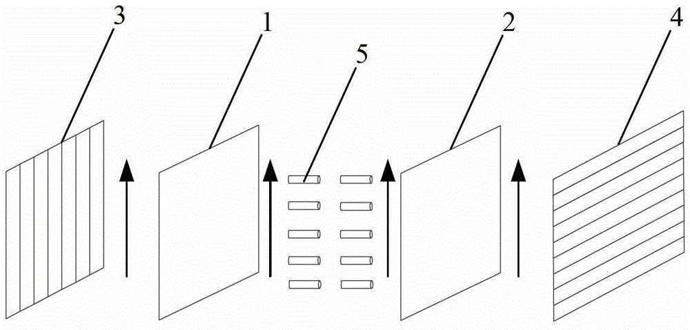
[0039] Obviously, in order to achieve the purpose of parallel incident of light rays into the array substrate along the same angle, not only a reflective layer and a light concentrating layer can be formed on one surface of the light guide plate, but also a reflective layer and a light concentrating layer can be arranged between the light guide plate and the array substrate. A multi-layer optical film, wherein the reflective layer is located under the light-gathering layer, and a plurality of small holes are arranged on the reflective layer. Its specific working principle is the same as that in the first embodiment. Similarly, the light concentrating layer can be designed to have a plurality of microlens structures, and the small holes on the reflective layer correspond to the positions of the microlens structures one by one, and are located at the focal point of the microlens structures, so that the light rays can be emitted from the light concentrating layer in parallel. The...

Embodiment 3

[0041] Correspondingly, this embodiment provides a backlight module, which includes a light guide plate and an optical film located above the light guide plate, wherein the light guide plate adopts the light guide plate in Embodiment 1, or the optical film adopts the light guide plate in Embodiment 2 The optical film can realize that the light is incident on the array substrate in parallel along the same angle, and no light is incident on the array substrate in other directions, thereby preventing light leakage caused by different viewing angles, while the light seen by the user from other viewing angles It is the result of the scattering of light at this angle on the surface of the display panel, ensuring that the brightness is the same when users watch the screen from different angles, thus overcoming the viewing angle dependence problem of TFT-LCD.


PUM


Abstract

The invention belongs to the technical field of display and discloses a light guide plate, an optical diaphragm, a backlight module, an array substrate and a liquid crystal module. A reflecting layer and a condensation layer are formed between the light guide plate and the array substrate, wherein the reflecting layer is located below the condensation layer; a plurality of small holes are formed in the reflecting layer; a point light source is formed the position of each small hole; light of the point light sources are converged by the condensation layer to form parallel light; the light enters the array substrate in parallel along the same angle; no light enters the array substrate in other directions; a backlight source with a higher condensation degree is provided for a TFT-LCD (thin film transistor-liquid crystal display), so that light leak caused by different visual angles is avoided; the light seen by a user from other visual angles is caused by surface scattering of the light at the angle on a display panel; the brightness is the same when the user watches a screen from different angles; and the problem of visual angle dependency of the TFT-LCD is solved.

Description

technical field [0001] The invention relates to the field of display technology, in particular to a light guide plate, an optical film, a backlight module, an array substrate and a liquid crystal module. Background technique [0002] Thin Film Transistor-Liquid Crystal Display (TFT-LCD) has the characteristics of small size, low power consumption, and no radiation. It has developed rapidly in recent years and occupies a dominant position in the current flat panel display market. Such as figure 1 As shown, the main structure of TFT-LCD is a liquid crystal module, which includes an array substrate 1 and a color filter substrate 2 in a box, and a polarizer 3 and a polarizer 4 are arranged on the two outer sides of the array substrate 1 and the color filter substrate 2 respectively. , and the polarization directions of the two polarizers are perpendicular. The display principle of TFT-LCD is as follows: the light passes through the polarizer 3 on the side of the array substrat...

Claims


Application Information

Patent Timeline
Patent Type & Authority Applications(China)
IPC IPC(8): F21V8/00F21V13/00F21S8/00G02F1/13357
CPCG02B6/0055G02F1/133603G02F1/133605G02F1/133606G02F1/133611G02F1/133607G02F1/133524
Inventor 秦广奎
Owner BOE TECH GRP CO LTD
Why Eureka
Try Eureka