Sealing device

A sealing device and side sealing technology, applied in the direction of engine sealing, rotating parts against centrifugal force, bearings, etc., can solve problems such as deterioration of sealing performance, and achieve the effect of preventing early wear

Inactive Publication Date: 2010-07-14
NOK CORP
View PDF1 Cites 6 Cited by
  • Summary
  • Abstract
  • Description
  • Claims
  • Application Information

AI Technical Summary

Problems solved by technology

However, on the other hand, since dust, muddy water, etc. enter the close-contact sliding portion S2, abrasion occurs between the radial lip 112 and the outer peripheral surface of the sleeve 121, which may cause deterioration of the sealing performance.

Method used


Image

  • Sealing device
  • Sealing device
  • Sealing device

Examples


Embodiment Construction

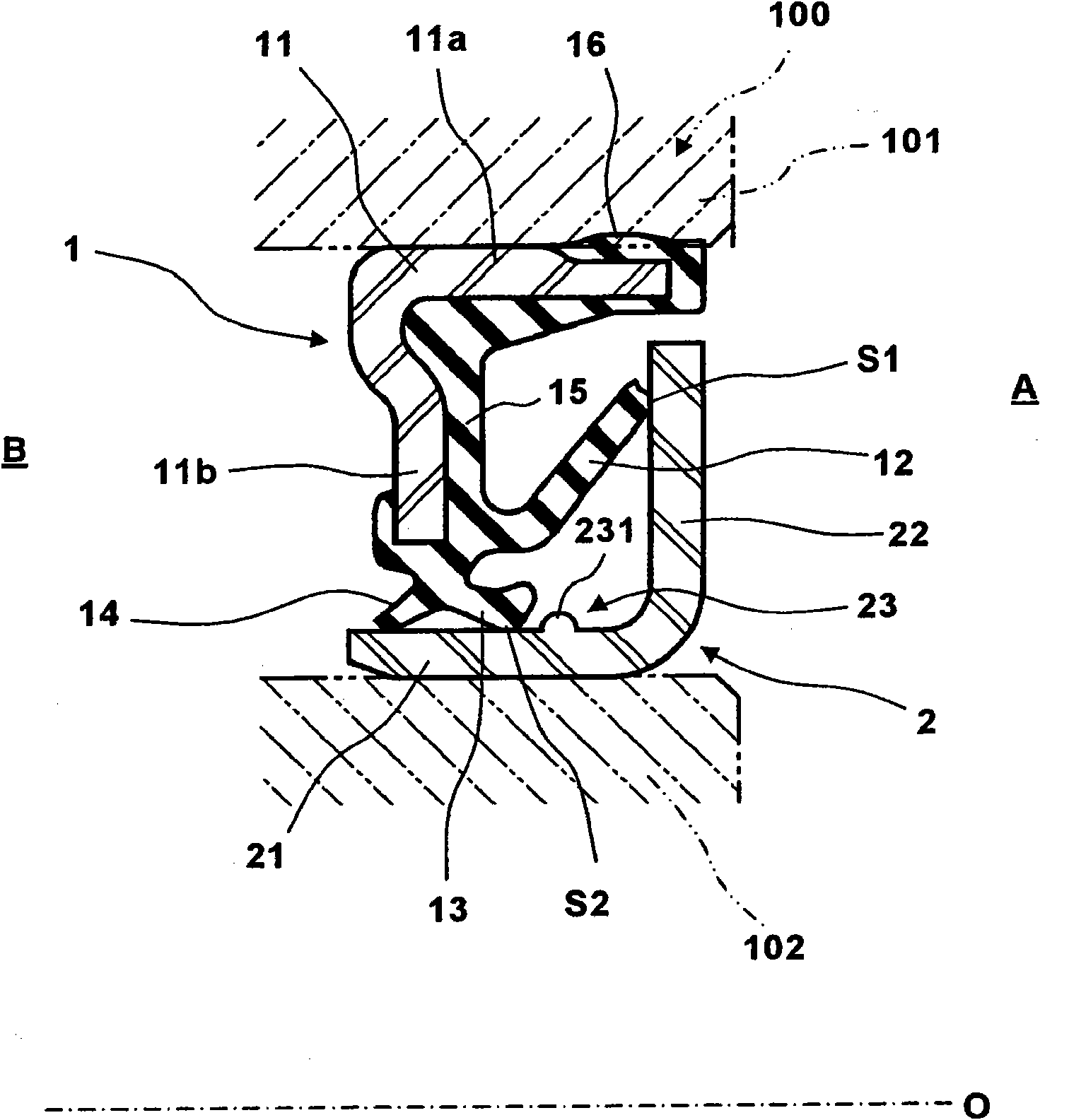
[0035] Hereinafter, preferred embodiments of the sealing device of the present invention will be described with reference to the accompanying drawings. figure 1 It is a half cross-sectional view of the first embodiment of the sealing device of the present invention taken on a plane passing through the axis O. FIG.

[0036] figure 1 The illustrated sealing device of the first embodiment includes a stationary side sealing element 1 mounted on the inner periphery of the outer ring 101 of the bearing 100 , and a flinger 2 mounted on the outer periphery of the inner ring 102 of the bearing 100 . In addition, the outer ring 101 corresponds to the stationary-side member described in claim 1 , and the inner ring 102 corresponds to the rotating-side member described in claim 1 .

[0037] The stationary side seal element 1 is composed of a metal mounting ring 11 , and a thrust lip 12 , a radial lip 13 , and a lubricating oil lip 14 integrally formed with the mounting ring 11 from a r...


PUM


Abstract

A sealing device for performing sealing by a throw off effect of a slinger (2). The sealing device is provided with a stationary sealing element (1) and the slinger (2) to prevent abrasion of an intimate contact slide section (S2) due to dust, muddy water, etc. and further prevent subsequent degradation of sealing ability of the sealing device caused by the abrasion. The stationary sealing element (1) has a thrust lip (12) and a radial lip (13) located on the radially inner side of the thrust lip (12) and is installed on a stationary member (101). The slinger (2) has a sleeve (21) fitted on a rotary member (102) and a flange (22) extending from one end of the sleeve (21). The thrust lip (12) is made to be in intimate slidable contact with the flange (22), and the radial lip (13) is made to be in intimate slidable contact with the outer peripheral surface of the sleeve (21). A circumferentially continuous dam (23) is provided on the outer peripheral surface of the sleeve (21) so as to be positioned on the flange (22) side of the intimate contact slide section (S2) of the radial lip (13). The dam (23) is a ridge (231) or a groove.

Description

technical field [0001] The present invention relates to a sealing device for preventing dust, muddy water, etc. from intruding into bearings, etc., in particular to a sealing device for sealing through the throwing action of an oil thrower. Background technique [0002] As one of the sealing devices for sealing the bearing, there is a sealing device having a slinger. Figure 4 is a typical prior art half-section view of such a seal, taken with a plane through the axis O. [0003] The sealing device includes: a stationary side sealing element 110 mounted on, for example, the inner circumference of a non-rotating outer ring 101 in a bearing 100; 122, wherein the sleeve 121 is fitted to the outer circumference of the inner ring 102 on the rotating side of the bearing 100. The thrust lip 111 provided on the static side sealing element 110 is slidably in close contact with the flange 122 of the slinger 120, and the radial lip 112 provided on the inner peripheral side of the thru...

Claims


Application Information

Patent Timeline
Patent Type & Authority Applications(China)
IPC IPC(8): F16J15/32F16C33/78
CPCF16J15/3264F16J15/164F16C33/7879F16C33/7883F16C33/7826F16C2300/02
Inventor 宗形忍
Owner NOK CORP
Why Eureka
Try Eureka