Bearing seal and swing device

A technology for bearing sealing and rotating devices, which is applied to the sealing of bearing components, shafts and bearings, and engines. It can solve the problems of reduced sealing performance, reduced durability of pin connections, replenishment of lubricating oil, and leakage of butter to reduce friction. , The effect of preventing the deterioration of sealing performance

Inactive Publication Date: 2006-06-07
KOMATSU LTD
View PDF1 Cites 8 Cited by
  • Summary
  • Abstract
  • Description
  • Claims
  • Application Information

AI Technical Summary

Problems solved by technology

[0019] In conjunction with the above description, in the conventional bearing sealing device described in the above-mentioned patent documents, although the sealing performance is generally good, there is a problem that the sealing performance is reduced when the vibration caused by the impact is applied.
[0020] In the sealing device having this type of inner seal, it is difficult for butter to leak from between the inner seal and the pin when the butter rises, and there is a problem that it is impossible to confirm the end of the rise of the butter.
[0021] In addition, if the sealing performance is lowered, there are problems that the durability of the pin connection will be reduced due to the easy penetration of sand and soil, and the leakage of lubricating oil, and the problem of frequent replenishment of lubricating oil.

Method used


Image

  • Bearing seal and swing device
  • Bearing seal and swing device
  • Bearing seal and swing device

Examples


no. 2 Embodiment approach

[0148] Next, a second embodiment of the present invention will be described. In addition, in the following description, the same reference numerals are used for the same members as those described above, and the description thereof will be omitted or simplified. In addition, in the cross-sectional views of the following embodiments, the right side will be described as the outer side of the rotating device, and the left side will be described as the inner side including the bearing portion.

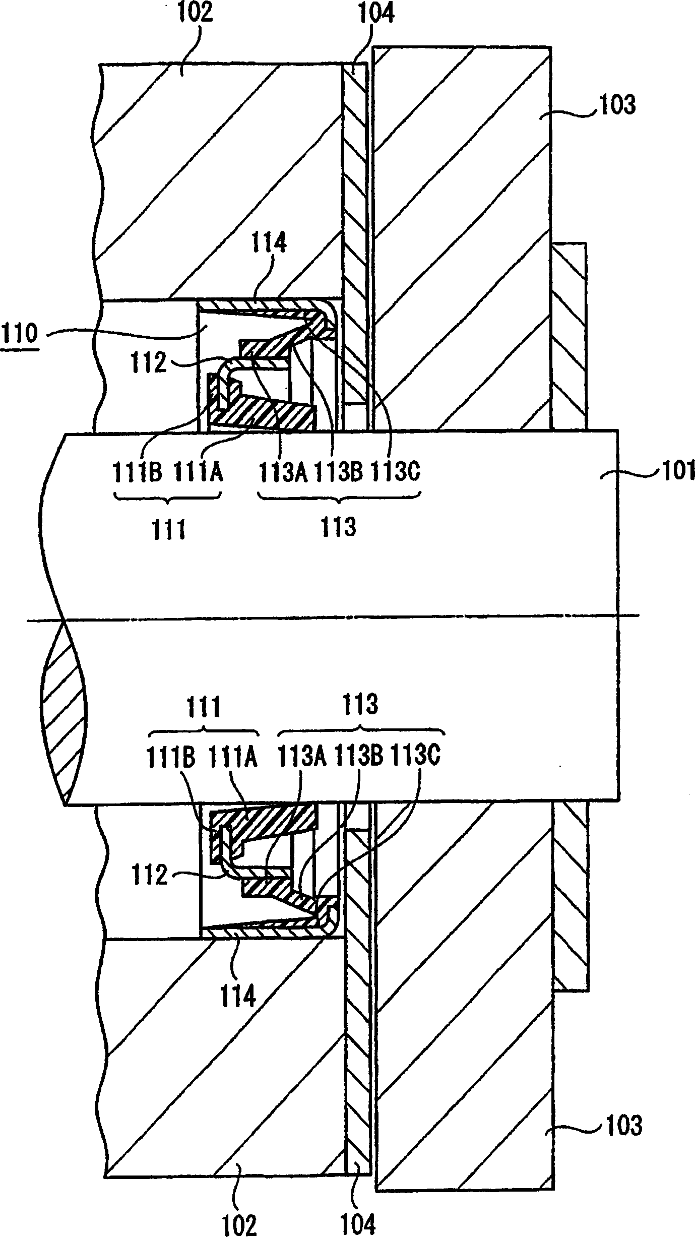
[0149] In the first embodiment described above, the outer seal 113 is configured such that the telescopic portion 113B protrudes in a direction inclined relative to the inner ring fixing portion 113A and the outer ring fixing portion 113C. It is configured to absorb displacement with respect to the shaft portion 101 and the boss 102 .

[0150] On the other hand, in the bearing seal 120 of the second embodiment, as Figure 5 As shown, there is a difference in the configuration of the oute...

no. 3 Embodiment approach

[0155] In the above-mentioned first embodiment, the outer seal 113 of the bearing seal 110 includes the inner ring fixing portion 113A, the expansion and contraction portion 113B, and the outer ring fixing portion 113C, and is configured to expand and contract by tilting relative to the axial direction of the shaft portion 101 . The portion 113B absorbs the displacement of the shaft portion 101 .

[0156] On the other hand, in the bearing seal 130 of the third embodiment, as Figure 6 As shown, the difference is that the outer seal 133 protrudes in a direction perpendicular to the axial direction of the shaft portion 101 , and has a constricted section at the center, and the constricted portion becomes a stretchable portion.

[0157] Furthermore, the bearing seal 110 of the above-mentioned first embodiment is configured such that the outer ring 114 has a substantially L-shaped cross-section, but in the bearing seal 130 of the third embodiment, the outer ring 134 is formed alon...

no. 7 Embodiment approach

[0203] In the sixth embodiment described above, the inner ring 362 is arranged to be sandwiched between the inner seal 361 and the outer seal 113 .

[0204] On the other hand, in the bearing seal 370 of the seventh embodiment, as Figure 14 As shown, the difference is that the inner ring 372 as an annular rigid part is embedded in the base of the inner seal 371 and integrated therewith. Also, the inner seal 371 and the outer seal 113 are adhesively fixed between mutual bases.

[0205] According to such a bearing seal 370 of the seventh embodiment, in addition to the effects of the above-described embodiment, the following effects are obtained.

[0206] That is, since the inner ring 372 is buried and integrated in the inner seal 371 , when the radial displacement of the sleeve 102 relative to the shaft portion 101 occurs, the effect of restraining the radial displacement of the inner seal 371 is further enhanced.


PUM


Abstract

A bearing seal and rotating device, comprising an outer seal that is easily displaced in the radial direction, an inner ring that is an annular rigid portion that does not extend in the radial direction, an inner seal with a sealing lip, and an outer ring that is arranged on the outer periphery of the outer seal Composition, and the elastic coefficient of the inner seal is set larger than the elastic coefficient of the outer seal. The ring-shaped rigid part is used as a boundary to ensure the tightness of the inner seal and the pin. When the radial displacement of the pin is displaced, the ring-shaped rigid part is integrally displaced by the inner seal following the displacement of the pin, and can be absorbed by the outer seal. Displacement of the ring-shaped rigid part.

Description

technical field [0001] The present invention relates to a bearing sealing device mainly used for pin-hinge connection of construction machines such as hydraulic excavators. Background technique [0002] In the hydraulic excavator of the construction machine, the swing is freely connected by the boom and the boom, the boom and the bucket or pins. [0003] In this way, in the pin-connected part, that is, in the pin-hinge connection, in general, lubricating oil such as grease (grease) is filled between the pin and the bushing to swing smoothly, and it is possible to prevent the pin from being resisted by the metal. Indirect wear and abnormal sound generation. [0004] In addition, to prevent sand and soil from entering between the pin and the bushing from the outside, and to prevent lubricating oil from leaking from the gap between the pin and the bushing, a bearing sealing device called a radial lip seal is used. [0005] As this bearing sealing device, for example, what is ...

Claims


Application Information

Patent Timeline
IPC IPC(8): F16C11/04F16C33/74F16J15/3224
Inventor 山本浩小村隆辅丸山纯
Owner KOMATSU LTD
Why Eureka
Try Eureka