
Control valve

A technology for controlling valves and valve bodies, which is applied in the control of coolant flow, valve details, multi-way valves, etc. It can solve problems such as valve sliding surface wear and achieve the effect of inhibiting early wear

Inactive Publication Date: 2020-10-09
YAMADA SEISAKUSHO KK
View PDF8 Cites 0 Cited by
  • Summary
  • Abstract
  • Description
  • Claims
  • Application Information

AI Technical Summary

Problems solved by technology

Therefore, in the above-mentioned conventional control valve, when the valve body is rotated while the sealing cylinder member is pressed by the outer peripheral surface of the valve body, there is a concern that the valve in the region where the protrusion height on the other end side of the sealing cylinder member is low may Early wear on sliding surfaces

Method used


Image

  • Control valve
  • Control valve
  • Control valve

Examples


Embodiment Construction

[0026] Next, embodiments of the present invention will be described based on the drawings. In the following description, a case where the control valve of the present embodiment is employed in a cooling system for cooling an engine using cooling water will be described.

[0027] [cooling system]

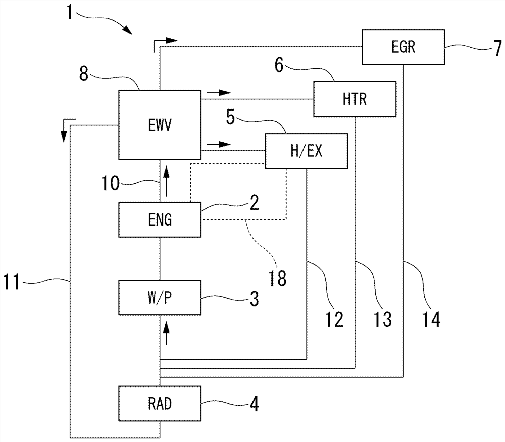
[0028] figure 1 is a block diagram of the cooling system 1.

[0029] Such as figure 1 As shown, the cooling system 1 is mounted on a vehicle having at least an engine as a driving source of the vehicle. In addition, as the vehicle, a hybrid vehicle, a plug-in hybrid vehicle, or the like may be used other than a vehicle having only an engine.

[0030] Cooling system 1 is engine 2 (ENG), water pump 3 (W / P), radiator 4 (RAD), heat exchanger 5 (H / EX), heat core 6 (HTR), EGR cooler 7 (EGR) and the control valve 8 (EWV) are configured by connecting various flow paths 10 to 14 .

[0031] The water pump 3 , the engine 2 , and the control valve 8 are sequentially connected on the main f...


PUM


Abstract

A control valve includes a casing, a valve body, and a seal cylinder member. The casing has an inlet and an outlet. The valve body is rotatably disposed inside the casing, and has a peripheral wall portion formed with a valve hole providing communicating between the inside and the outside. One end portion of the seal cylinder member communicates with a downstream side of the outlet, and a valve sliding contact surface is provided at the other end portion. A protruding height of the other end portion of the seal cylinder member continuously changes in a circumferential direction thereof to conform to a shape of an outer circumferential surface of the circumferential wall portion. A region of the other end portion of the seal cylinder member where the protruding height is lower is provided with a thick portion that is thicker than other portions and reaches the valve-sliding contact surface.

Description

technical field [0001] The present invention relates to a control valve used for channel switching and the like of cooling water for vehicles. Background technique [0002] In a cooling system that uses cooling water to cool the engine, in addition to the radiator flow path that circulates between the radiator and the engine, a bypass flow path that bypasses the radiator and a warm water flow that passes through the oil heater are sometimes provided. machine flow etc. In such a cooling system, a control valve is interposed at a branch portion of the flow path, and the flow path is appropriately switched by the control valve. As a control valve, it is known that a cylindrical valve body is rotatably arranged in a housing, and an arbitrary flow path is opened and closed corresponding to the rotational position of the valve body (for example, refer to Japanese Patent Application Laid-Open No. 2017-3064 (hereinafter referred to as patent). Document 1)). [0003] The control v...

Claims


Application Information

Patent Timeline
Patent Type & Authority Applications(China)
IPC IPC(8): F16K11/085F16K27/06F01P7/14F01P7/16
CPCF16K11/0856F16K27/065F01P7/14F01P7/165F01P2007/146F01P2050/22F16K11/085F16K5/0464F16K5/181F16K31/002
Inventor 大关哲史永井淑仁
Owner YAMADA SEISAKUSHO KK
Learn More