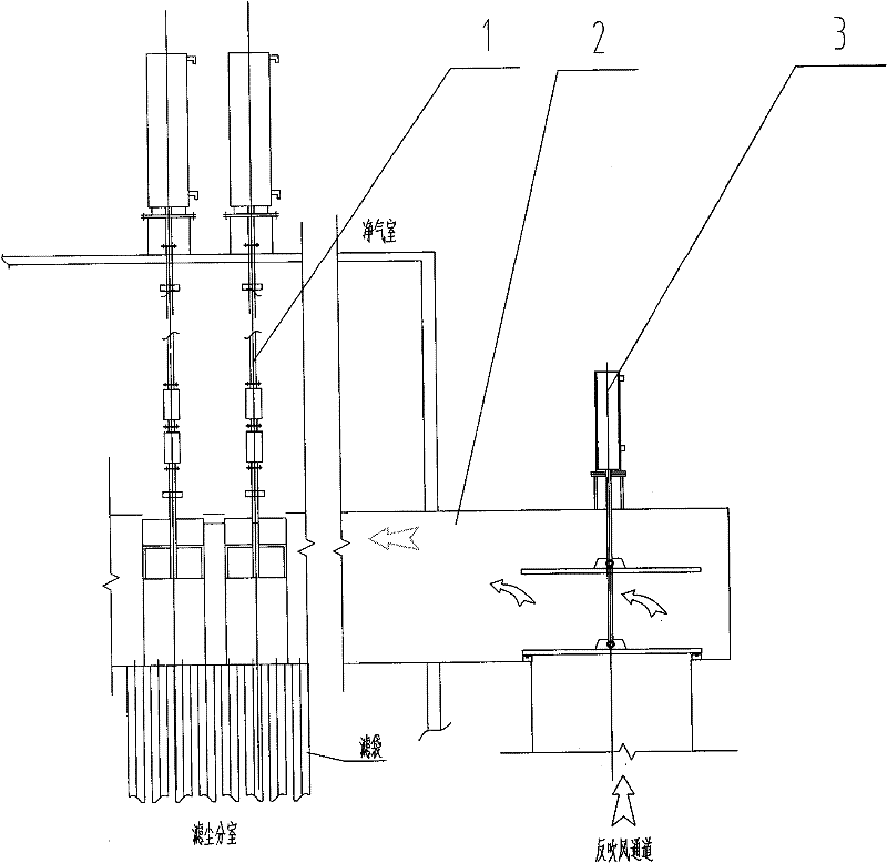
Instantaneous-blowing deashing unit and control method thereof for chamber blowback bag filter
A technology of bag dust collector and compartment back blowing, which is applied in the field of instant blowing and dust removal devices and dust removal devices, which can solve the problems of poor dust removal effect and achieve good dust removal ability, simple structure and convenient adjustment.
- Summary
- Abstract
- Description
- Claims
- Application Information
AI Technical Summary
Problems solved by technology
Method used
Image
Examples
Embodiment 1
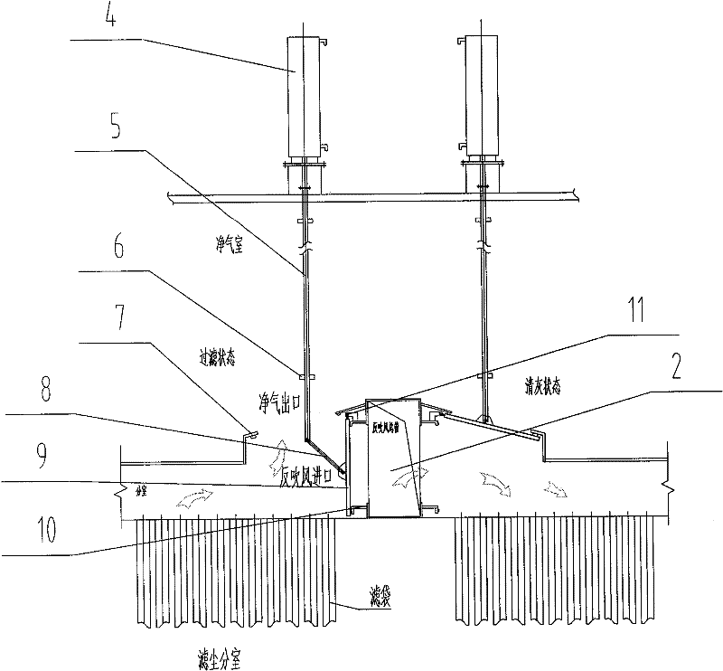
[0046] Such as figure 2 As shown, the reverse blowing inlet is provided on the side wall of the reverse blowing main pipe 2 . The link mechanism includes a main rod 5 , a secondary rod 8 and a rotating shaft 11 . The main rod 5 is fixedly connected with the cylinder 4 . The auxiliary rod 8 is connected with the movable shaft of the valve plate 9 . The main rod 5 and the secondary rod 8 are connected by a movable shaft. The rotating shaft 11 is arranged between the clean air outlet and the reverse blowing inlet. One end of the valve plate 9 is pivotally connected to the rotating shaft 11, so that the valve plate 9 can rotate along the rotating shaft 11 to switch to the clean air outlet or the reverse blowing inlet.
[0047] The connecting rod mechanism designed in this embodiment is to push the auxiliary rod 8 through the up and down movement of the main rod 5, and then drive the valve plate 9 to rotate along the rotating shaft 11, so as to realize the switching action of ...
Embodiment 2
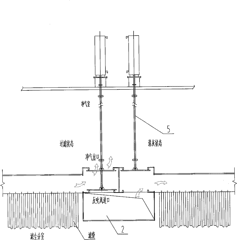
[0049] Such as image 3 Shown, described anti-blowing inlet is opened on the top or the following of anti-blowing main pipe 2. The clean air outlet is set correspondingly to the reverse blowing inlet. This link mechanism is only made up of one main rod 5 and gets final product. The main rod 5 is fixedly connected with the cylinder 4 and the valve plate 9 respectively. The valve plate 9 realizes switching between the clean air outlet and the reverse blowing inlet through the up and down movement of the main rod 5 .
[0050] This embodiment is suitable for projects with implementation conditions, that is, the reverse blowing main pipe 2 has enough width to be provided with reverse blowing inlets above and below it. The advantage of this scheme is that on the one hand, it simplifies the structure of the cleaning device, which further reduces the engineering cost of the device; The filter bag can be overhauled.
Embodiment 3
[0052] Such as Figure 4 As shown, the structure of this embodiment is basically the same as that of the first embodiment, except that a reverse blowing air inlet butterfly valve 12 is provided on the side wall of the reverse blowing main pipe 2 . The effect of the reverse blowing air inlet butterfly valve 12 is to close and open the reverse blowing. This mode of implementation is mainly aimed at the project of transformation, and the dust cleaning device designed by the cost patent can still be transformed on the basis of not dismantling the reverse blowing air inlet butterfly valve 12 of the original equipment.
[0053] Figure 5 It is the specific soot removal control flow chart of the flash blowing soot cleaning device for the compartmental reverse blowing bag filter designed for the above. Such as Figure 5 As shown, the ash removal control method based on the above-mentioned instant blowing ash removal device includes the following specific steps:
[0054] (1) When t...
PUM
 Abstract
Description
Claims
Application Information
 - R&D
- Intellectual Property
- Life Sciences
- Materials
- Tech Scout
- Unparalleled Data Quality
- Higher Quality Content
- 60% Fewer Hallucinations
Browse by: Latest US Patents, China's latest patents, Technical Efficacy Thesaurus, Application Domain, Technology Topic, Popular Technical Reports.
© 2025 PatSnap. All rights reserved.Legal|Privacy policy|Modern Slavery Act Transparency Statement|Sitemap|About US| Contact US: help@patsnap.com


