Instantaneous-blowing deashing unit and control method thereof for chamber blowback bag filter

A technology of bag dust collector and compartmental blowback, which is applied in the field of dust removal device and instant blowing dust removal device, which can solve the problems of poor dust removal effect and achieve the effect of good dust removal ability, simple structure and convenient adjustment

Active Publication Date: 2010-07-28
山川秀美生态环境工程股份有限公司
View PDF2 Cites 10 Cited by
  • Summary
  • Abstract
  • Description
  • Claims
  • Application Information

AI Technical Summary

Problems solved by technology

This is the back blowing used for filter bag dust removal in this type of technology is a stable pressure and continuous back blowing air flow, and its stable flow of dust removal air flow has a poor cleaning effect on filter bags.

Method used


Image

  • Instantaneous-blowing deashing unit and control method thereof for chamber blowback bag filter
  • Instantaneous-blowing deashing unit and control method thereof for chamber blowback bag filter
  • Instantaneous-blowing deashing unit and control method thereof for chamber blowback bag filter

Examples


Embodiment 1

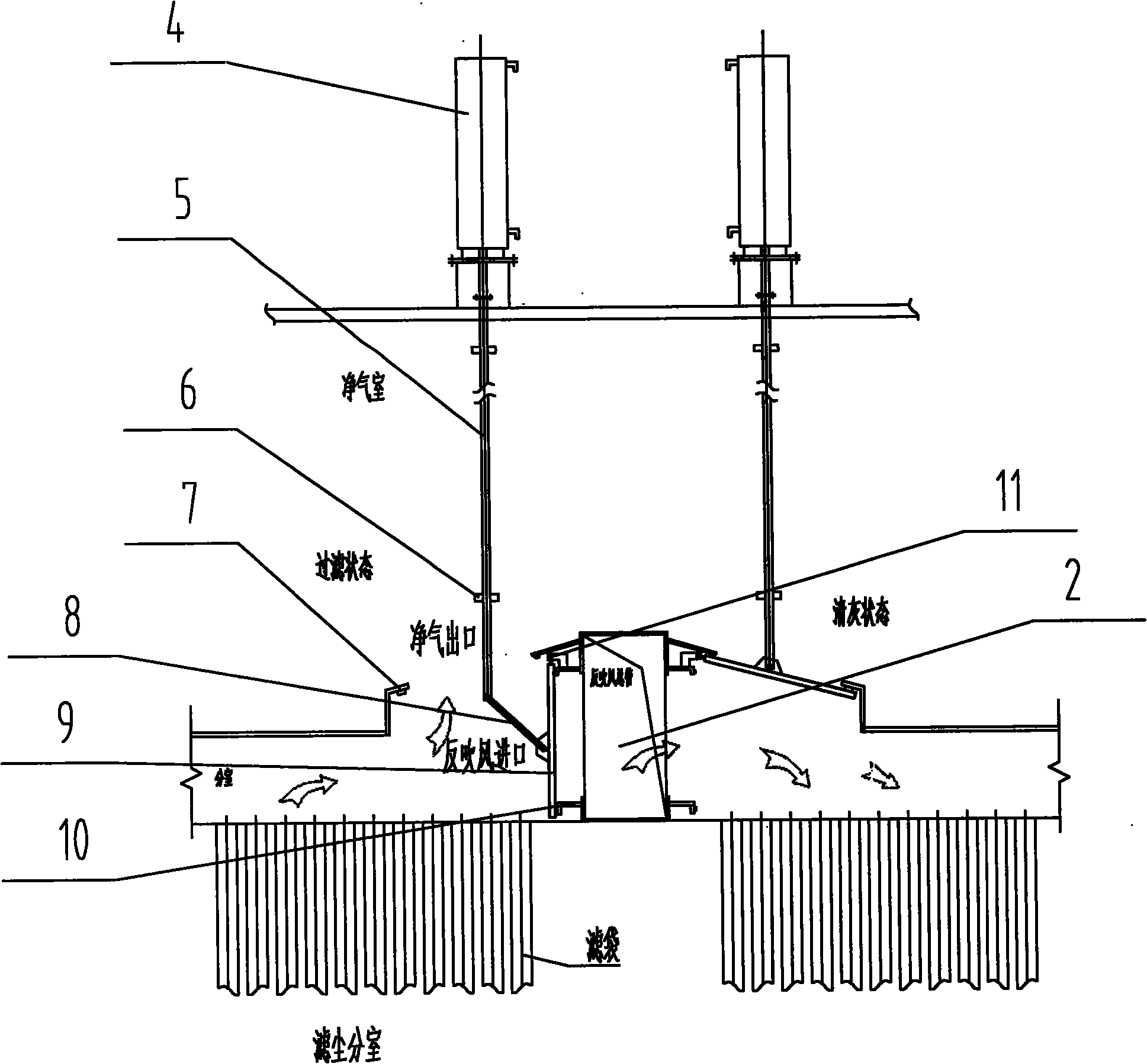
[0046] Such as figure 2 As shown, the reverse blowing inlet is provided on the side wall of the reverse blowing main pipe 2 . The link mechanism includes a main rod 5 , a secondary rod 8 and a rotating shaft 11 . The main rod 5 is fixedly connected with the cylinder 4 . The auxiliary rod 8 is connected with the movable shaft of the valve plate 9 . The main rod 5 and the auxiliary rod 8 are connected by a movable shaft. The rotating shaft 11 is arranged between the clean air outlet and the reverse blowing inlet. One end of the valve plate 9 is pivotally connected to the rotating shaft 11, so that the valve plate 9 can rotate along the rotating shaft 11 to switch to the clean air outlet or the reverse blowing inlet.

[0047] The connecting rod mechanism designed in this embodiment is to push the auxiliary rod 8 through the up and down movement of the main rod 5, and then drive the valve plate 9 to rotate along the rotating shaft 11, so as to realize the switching action of ...

Embodiment 2

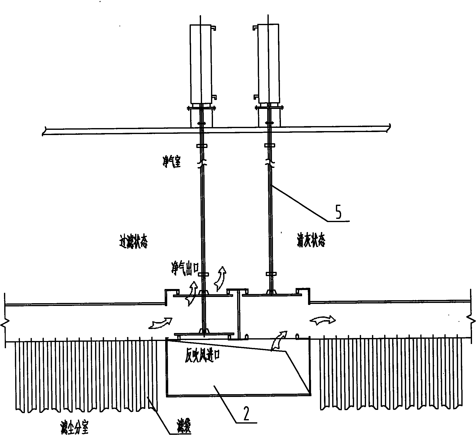
[0049] Such as image 3 Shown, described anti-blowing inlet is opened on the top or the following of anti-blowing main pipe 2. The clean air outlet is set correspondingly to the reverse blowing inlet. This link mechanism is only made up of one main rod 5 and gets final product. The main rod 5 is fixedly connected with the cylinder 4 and the valve plate 9 respectively. The valve plate 9 realizes switching between the clean air outlet and the reverse blowing inlet through the up and down movement of the main rod 5 .

[0050] This embodiment is suitable for projects with implementation conditions, that is, the reverse blowing main pipe 2 has enough width to be provided with reverse blowing inlets above and below it. The advantage of this scheme is that on the one hand, it simplifies the structure of the cleaning device, which further reduces the engineering cost of the device; The filter bag can be overhauled.

Embodiment 3

[0052] Such as Figure 4 As shown, the structure of this embodiment is basically the same as that of the first embodiment, except that a reverse blowing air inlet butterfly valve 12 is provided on the side wall of the reverse blowing main pipe 2 . The effect of the reverse blowing air inlet butterfly valve 12 is to close and open the reverse blowing. This mode of implementation is mainly aimed at the project of transformation, and the dust cleaning device designed by the cost patent can still be transformed on the basis of not dismantling the reverse blowing air inlet butterfly valve 12 of the original equipment.

[0053] Figure 5 It is the specific soot cleaning control flow chart of the instant blowing soot cleaning device for the chamber reverse blowing bag filter designed for the above. Such as Figure 5 As shown, the ash removal control method based on the above-mentioned instant blowing ash removal device includes the following specific steps:

[0054] (1) When the ...


PUM


Abstract

The invention provides an instantaneous-blowing deashing unit for a chamber blowback bag filter, comprising a blowback header pipe, an instantaneous-blowing valve and a plurality of single-plate two-way scavenging air valves, wherein the blowback header pipe is arranged in the middle channel of the chamber blowback bag filter, a plurality of dust filter chambers are arranged at both sides of the chamber blowback bag dust filter, each single-plate two-way scavenging air valve is installed corresponding to each dust filter chambers, the instantaneous-blowing valve is arranged on one end of the blowback header pipe to control a valve between the blowback header pipe and a blowback air source channel to open or close, the single-plate two-way scavenging air valve is a three-way valve, and the valve plates which are connected with a cylinder by a connection mechanism are driven and controlled by the cylinder which is driven by the connection mechanism. The instantaneous-blowing deashing unit enables the bag filter to switch between a filter state and a deashing state by a simple structure, and the design of the instantaneous-blowing valve enables the blowback of the deashing unit to be with certain detonation effect, thereby realizing better deashing capacity.

Description

technical field [0001] The invention relates to a dust cleaning device for a bag filter, in particular to a flash blow cleaning device applied to an external filter type compartment bag filter. The dust cleaning device realizes detonation back blowing through a simple structure Dust removal, better dust removal effect has been obtained. The invention also relates to a dust removal control method of the dust removal device, which belongs to the technical field of bag dust removal. Background technique [0002] In the bag type dust removal technology, the cleaning of the filter bag is the most important and critical link, and it is also the most important feature to distinguish the bag type dust removal technology route. At present, the most widely used external filter bag dust removal technology is mainly divided into two categories: one is the pulse jet cleaning technology with pulse valve device for strong cleaning, and the other is weak cleaning technology. Ash cleaning ...

Claims


Application Information

Patent Timeline
Patent Type & Authority Applications(China)
IPC IPC(8): B01D46/04B01D46/42
Inventor 李风录杨汉东
Owner 山川秀美生态环境工程股份有限公司
Why Eureka
Try Eureka