Liquid crystal display device
A technology of liquid crystal display device and liquid crystal display panel, which is applied to static indicators, nonlinear optics, instruments, etc., can solve problems such as complicated operation, and achieve the effect of suppressing chromaticity deviation
- Summary
- Abstract
- Description
- Claims
- Application Information
AI Technical Summary
Problems solved by technology
Method used
Image
Examples
Embodiment 1
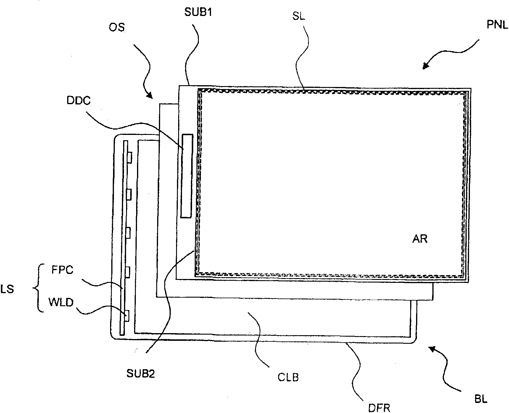
[0063] figure 2 It is a schematic diagram showing Example 1 of the liquid crystal display device of the present invention, and shows a plan view in a disassembled state of the liquid crystal display device.
[0064] exist figure 2 In the figure, the liquid crystal display device is configured by arranging a liquid crystal display panel PNL, an optical sheet OS, and a backlight BL from the viewer side (the paper surface).
[0065] The liquid crystal display panel PNL is configured by encapsulating substrates SUB1 and SUB2 which are opposed to each other with liquid crystal interposed therebetween, and incorporates an image display section AR including a plurality of pixels. In addition, liquid crystal is sealed between the substrates SUB1 and SUB2 by the sealing material SL formed to surround the image display portion AR, and fastening between the substrates SUB1 and SUB2 is achieved.
[0066] Although not shown in the figure, the image display unit AR is composed of a plural...
Embodiment 2
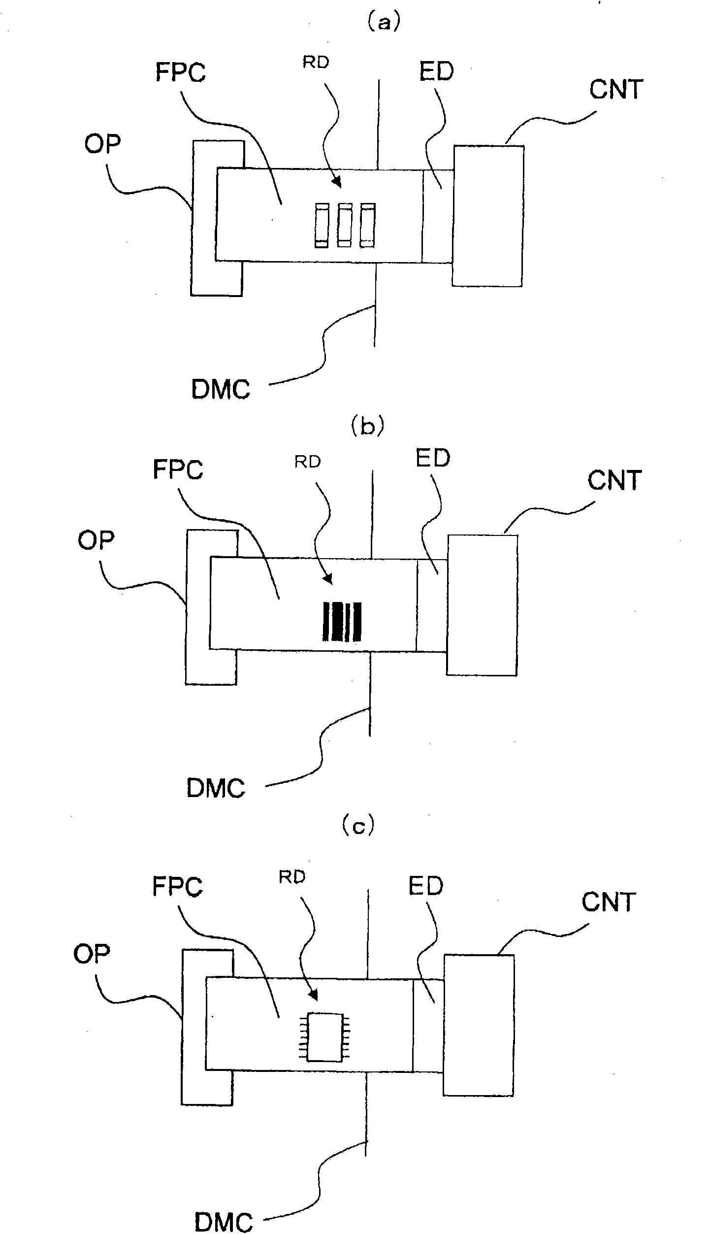
[0084] In the above-mentioned embodiment, in the information RD representing the level of whiteness tolerance of the light source LS of the backlight BL such as figure 1 In the embodiment shown in (c) stored in a storage device composed of a semiconductor device, the information RD stored in the storage device is read by a person, and the person adjusts the gamma of the image signal input to the liquid crystal display panel PNL based on the information RD. Ma characteristics are corrected.
[0085] However, the storage device may be electrically connected to the image quality processing circuit QMC for correcting the gamma characteristic of the image signal, and the gamma characteristic of the image signal may be automatically corrected based on the information RD stored in the storage device. . In this case, since there is no need for human beings to read the information RD stored in the above-mentioned storage device, it is not necessary to figure 1 As shown in (c), it mus...
Embodiment 3
[0087] In the above example, if Figure 4As shown, in the state where the flexible circuit board FPC is connected to the connector CNT, the information RD indicating the level of whiteness tolerance of the light source LS of the backlight BL is expressly displayed on the visible surface of the flexible circuit board FPC. However, such explicit indication may be made on the surface opposite to the above-mentioned surface of the flexible circuit board FPC, for example, the surface corresponding to the front and back. This is because the displayed information can be confirmed before the flexible circuit board FPC is connected to the connector CNT.
PUM
 Abstract
Description
Claims
Application Information
 - R&D
- Intellectual Property
- Life Sciences
- Materials
- Tech Scout
- Unparalleled Data Quality
- Higher Quality Content
- 60% Fewer Hallucinations
Browse by: Latest US Patents, China's latest patents, Technical Efficacy Thesaurus, Application Domain, Technology Topic, Popular Technical Reports.
© 2025 PatSnap. All rights reserved.Legal|Privacy policy|Modern Slavery Act Transparency Statement|Sitemap|About US| Contact US: help@patsnap.com


