Pivoting structure of tool storage cabinet

A technology for tool storage and synchronous rotation, applied in the field of pivoting structures, can solve the problems of laborious turning, less tool slots, tool falling, etc.

Inactive Publication Date: 2010-08-18
谢智庆
View PDF0 Cites 0 Cited by
  • Summary
  • Abstract
  • Description
  • Claims
  • Application Information

AI Technical Summary

Problems solved by technology

However, its large-area contact causes the toolbox to have a large friction coefficient when turning, which makes it difficult to turn, and the hand tools can accommodate fewer tool slots, and there is no avoidable separation when placed on the outer edge of the cylindrical toolbox. Protective design, easy to drop the tools in each tool slot due to vibration or collision

Method used


Image

  • Pivoting structure of tool storage cabinet
  • Pivoting structure of tool storage cabinet
  • Pivoting structure of tool storage cabinet

Examples


Embodiment Construction

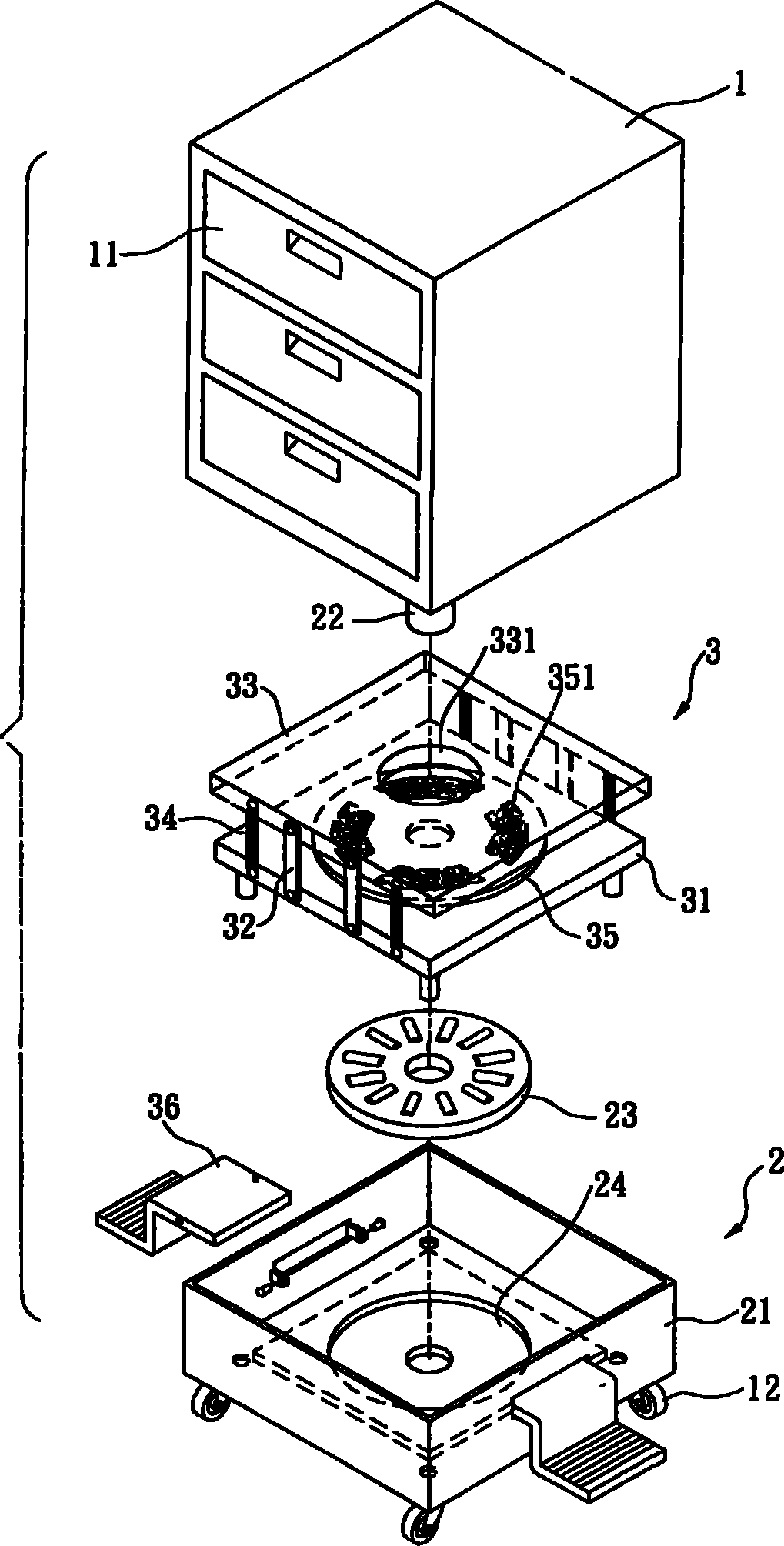
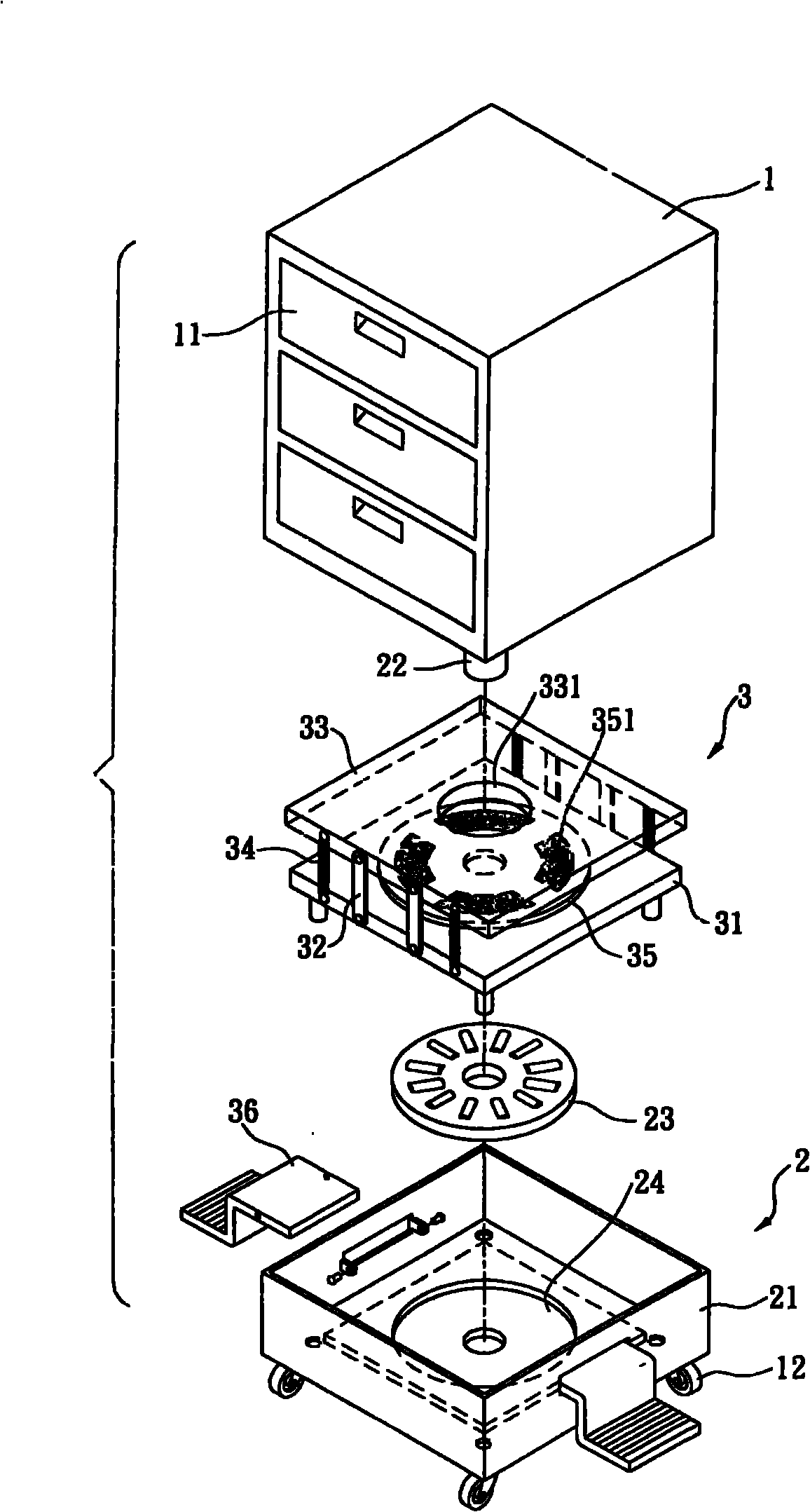
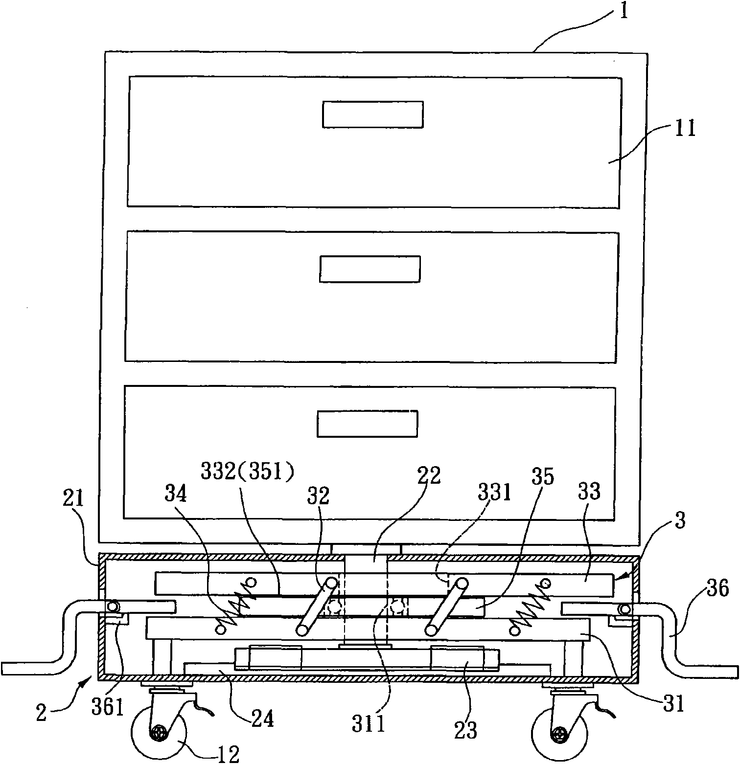
[0025] Please refer to FIG. 1 to FIG. 7 , which show the structure of the selected embodiment of the present invention.

[0026] The present invention is a pivoting structure of a tool storage cabinet, which has more than two wheel bodies that can roll along a circular track, or in a way that the pivot joints can be rotated, so that a tool storage cabinet can be rotated by external force And can do autorotation, and can reduce the radius of gyration required when turning.

[0027] The tool storage cabinet is a box-shaped or cabinet-shaped body, which can be used to store hand tools or electric tools through the design of storage structures such as storage chambers or drawers, so that users can take them out and use them according to their needs.

[0028] The above-mentioned rotating device is a controllable wheel set, which has more than one wheel body, and each wheel body can be adjusted to roll forward, backward or turn, or be adjusted to roll along a circular track. Driven...


PUM


Abstract

The invention relates to a pivoting structure of a tool storage cabinet. The pivoting structure enables the tool storage cabinet to make rotation by means of external force, a rotating device is carried out by a wheel set, and then the invention achieves the purpose that the tool storage cabinet can reduce the gyration radius required for rotating, wherein each wheel body of the wheel set can roll along a circular trace due to angle adjustment.

Description

technical field [0001] The invention relates to a pivoting structure of a tool storage cabinet. Background technique [0002] In order to cooperate with the operation of various tasks to make the tools easy to place or take, generally a toolbox or box or cabinet with accommodating function is used to store various tools. The bottom of a general toolbox or cabinet is provided with multiple wheels for the user to push and shift the cabinet to a predetermined location. However, in some narrow spaces, when the tool is taken out and used, it is often difficult due to the opening direction of the drawer or door. There is a fixed direction, which in turn causes the user to remain unchanged. At this time, it is necessary to turn the toolbox or cabinet to find a convenient direction of use. The range of rotation of the wheels will interfere with each other. Therefore, how to effectively reduce the Rotating the range to adapt to the narrow space is the problem that the related indust...

Claims


Application Information

Patent Timeline
Patent Type & Authority Applications(China)
IPC IPC(8): B25H3/00
Inventor 谢智庆
Owner 谢智庆
Why Eureka
Try Eureka