Wrench suitable for T-shaped groove of cast iron platform

A technology of cast iron platform and wrench, which is applied in the field of wrenches, which can solve the problems of wrench hurting hands and hexagonal bolts unable to reach the tightening torque, so as to avoid time-consuming problems, improve operation safety, and automatically adjust the tightening torque.

Active Publication Date: 2021-10-19
HENAN UNIV OF SCI & TECH
View PDF13 Cites 0 Cited by
  • Summary
  • Abstract
  • Description
  • Claims
  • Application Information

AI Technical Summary

Problems solved by technology

The existing large-scale cast iron platforms are mainly T-slot platforms. When fixing the equipment on the cast iron platform, bolts are required for connection. However, due to the special structure of the T-slot, the traditional external hexagonal bolts cannot achieve the required tightening torque. On the one hand, it is difficult to buy special T-bolts; on the other hand, the price is 5-10 times that of hexagonal bolts.
In addition, for the traditional wrench, its working direction coincides with the working surface of the cast iron platform, and there is a risk of injury to the hand when using the wrench

Method used


Image

  • Wrench suitable for T-shaped groove of cast iron platform
  • Wrench suitable for T-shaped groove of cast iron platform
  • Wrench suitable for T-shaped groove of cast iron platform

Examples


Embodiment 1

[0034] Embodiment 1: In this embodiment, the rotation axis of the clamping mechanism and the rotation axis of the power part are vertical in the space, that is, when the clamping mechanism is screwing the bolt, the rotation axis of the clamping mechanism is a vertical axis, perpendicular to the cast iron The surface of the platform, at this time, the axis of rotation of the power part is horizontal and parallel to the surface of the cast iron platform.

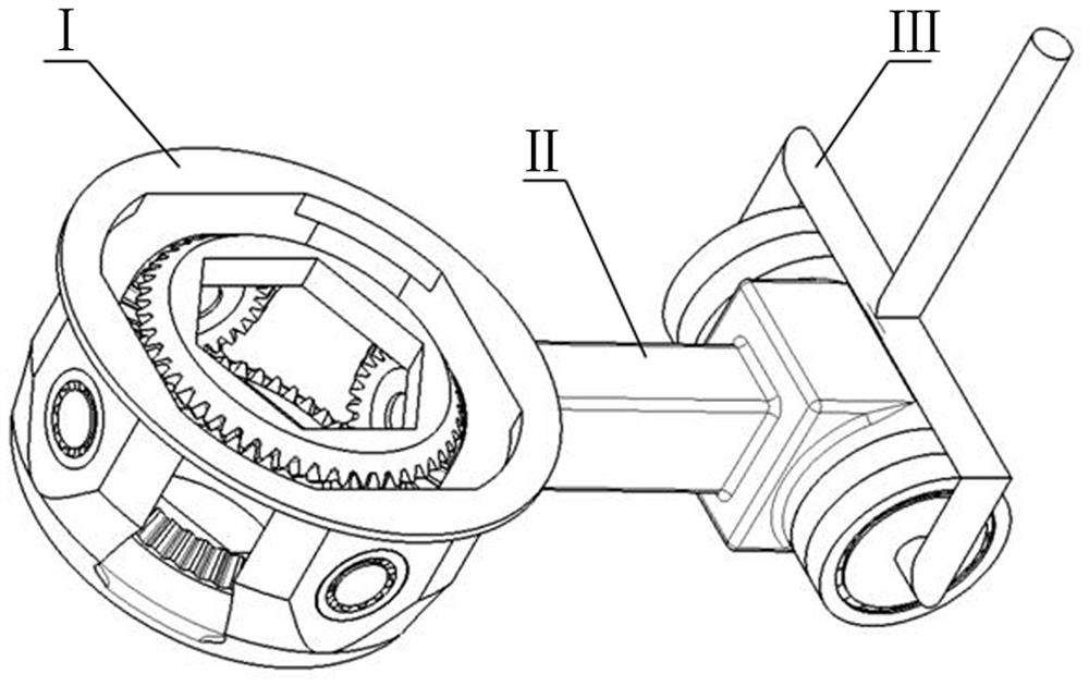
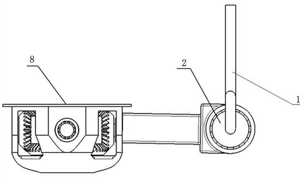
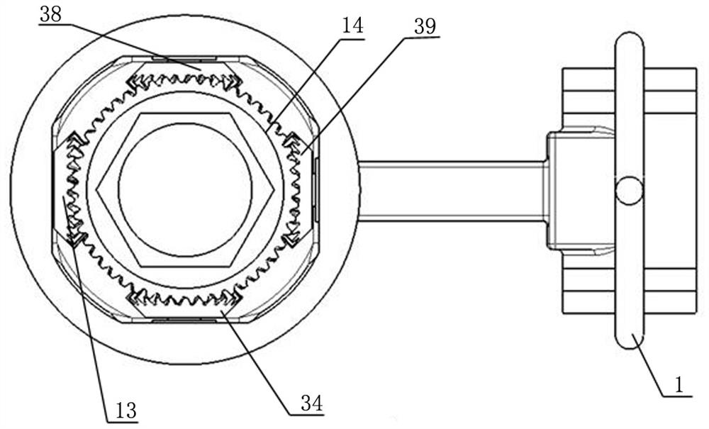
[0035] For the structure of the wrench in this embodiment, please refer to the attached Figure 2-7 , the working part is provided with a hollow clamping shell 8 for accommodating the clamping mechanism, and the upper and lower end surfaces of the clamping shell 8 are respectively provided with through holes for bolts to pass through. The clamping mechanism includes a second fixed helical gear 14 located at the upper end of the clamping housing 8 and a first fixed helical gear 9 located at the lower end of the clamping housing...

Embodiment 2

[0051] Embodiment 2: as Figure 8-11 , in this embodiment, the rotation axis of the clamping mechanism and the rotation axis of the power part are parallel in space, that is, when the clamping mechanism is screwing the bolt, the rotation axis of the clamping mechanism is a vertical axis, perpendicular to the surface of the cast iron platform, At this time, the rotation axis of the power part is also perpendicular to the surface of the cast iron platform. However, due to the setting of the second transmission shaft, the rotation axis of the power part is away from the cast iron platform.

[0052] At this time, the handle 1 can be set in an L-shape, one end is connected to the inner ring of the reversing bearing at one end of the reversing housing, and the other end is used as a handle, so that the handle is higher than the surface of the cast iron platform, and it can be avoided during work. Open cast iron platform, thereby improving the safety of wrench use.

[0053] In this...


PUM


Abstract

The invention discloses a wrench suitable for a T-shaped groove of a cast iron platform. The wrench comprises a working part used for clamping and screwing a bolt, a power part serving as a power source and a transmission part connected with the working part and the power part, wherein the power part is rotationally arranged at one end of the transmission part; the working part is arranged at the other end of the transmission part; a clamping mechanism used for clamping the bolt is rotationally arranged in the working part; the rotating axis of the power part is located in a plane parallel to the rotating axis of the clamping mechanism; the transmission part is provided with a reversing transmission mechanism; and the reversing transmission mechanism is used for reversing rotating power of the power part and driving the clamping mechanism to rotate. According to the wrench, a handle can be operated outside the cast iron platform, so that a conventional outer hexagon bolt reaches the required tightening torque.

Description

technical field [0001] The invention belongs to the technical field of wrenches, in particular to a wrench suitable for a T-shaped groove of a cast iron platform. Background technique [0002] The cast iron platform is widely used in the measurement, inspection and marking of machining workpieces, precision equipment assembly, welding and assembly of sheet metal parts, motor fatigue test basis, wind power test basis and other fields. It is machinery manufacturing and processing industry equipment. The existing large-scale cast iron platforms are mainly T-slot platforms. When fixing the equipment on the cast iron platform, bolts are required for connection. However, due to the special structure of the T-slot, the traditional hexagonal bolts cannot achieve the required tightening torque. On the one hand, the special T-bolts are difficult to buy, on the other hand, the price is 5-10 times that of the outer hexagonal bolts. In addition, for the traditional wrench, its working ...

Claims


Application Information

Patent Timeline
Patent Type & Authority Applications(China)
IPC IPC(8): B25B13/46B25B23/16
CPCB25B13/46B25B23/16
Inventor 谢成伟郭志军吴静波王永巍刘军杰经博文
Owner HENAN UNIV OF SCI & TECH
Why Eureka
Try Eureka