
Signal receiving device and frequency determining circuit

A technology of a signal receiving device and a judgment circuit, which is applied in the direction of angle demodulation through phase difference detection, etc., and can solve problems such as the continuous unlocking state of the category indication and the inability to reach the locked state

Active Publication Date: 2012-12-12
REALTEK SEMICON CORP
View PDF0 Cites 0 Cited by
  • Summary
  • Abstract
  • Description
  • Claims
  • Application Information

AI Technical Summary

Problems solved by technology

If it is beating frequently, the category indicator will even continue to be in the unlocked state or cannot reach the locked state

Method used

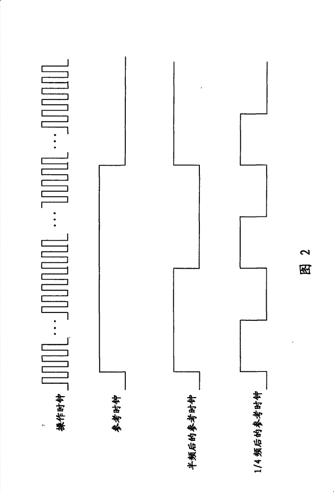
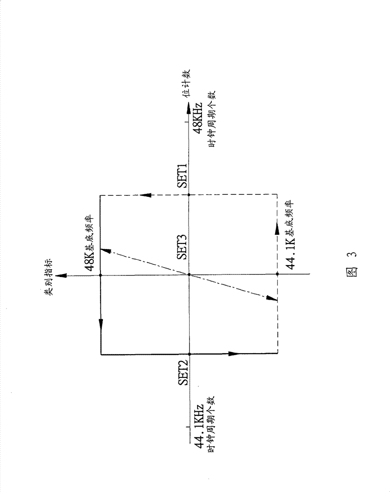

Image

  • Signal receiving device and frequency determining circuit
  • Signal receiving device and frequency determining circuit
  • Signal receiving device and frequency determining circuit

Examples


Embodiment Construction

[0030] The aforementioned and other technical contents, features and effects of the present invention will be clearly presented in the following detailed description of an embodiment with reference to the drawings.

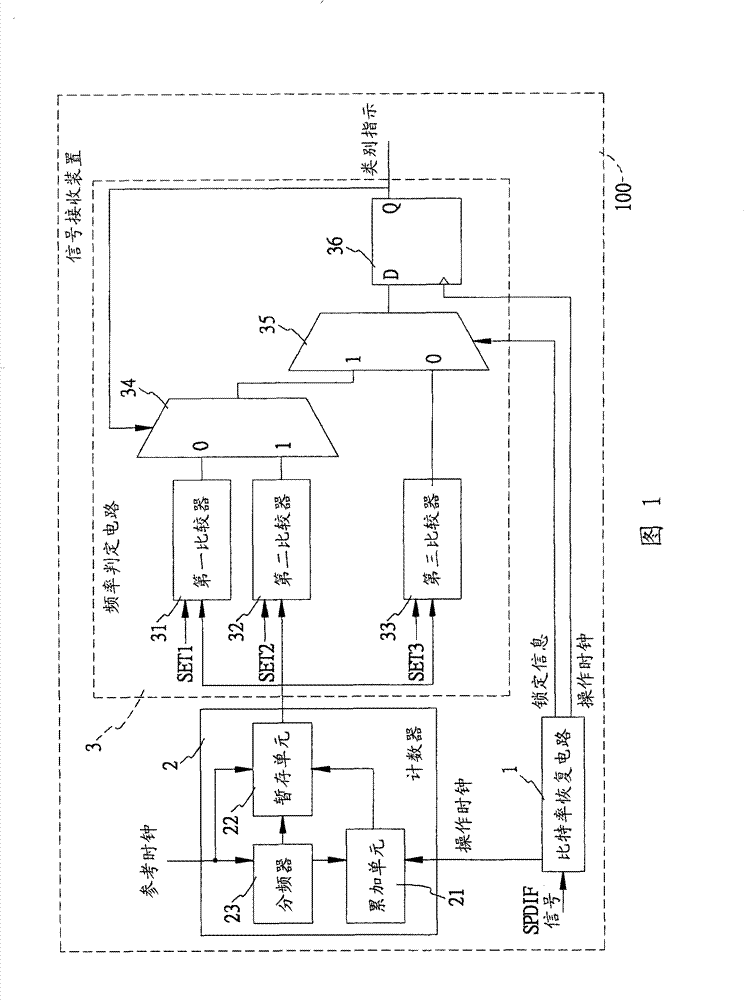
[0031] An embodiment of the signal receiving device of the present invention is suitable for receiving a signal to be determined with a plurality of bits and outputting a type indication which is beneficial for audio processing. In this example, the signal to be determined is an SPDIF signal, which mainly supports the first type (48K) base frequency and the second type (44.1K) base frequency. When the type indication is 1, it means that the SPDIF signal is determined to have the first type of base frequency; when the type indication is 0, it means that the SPDIF signal is determined to have the second type of base frequency.

[0032] refer to figure 1 , this embodiment includes a bit rate recovery (bit-rate recovery) circuit 1, a counter 2 and a frequency determi...


PUM


Abstract

The invention relates to a signal receiving device and a frequency determining circuit. The signal receiving device is suitable for receiving a multi-bit signal to be determined that supports a first type of base frequency or a second type of base frequency, and outputting a type indicator for indicating the signal to be determined to support the first type of base frequency or the second type ofbase frequency; the signal receiving device comprises a counter and a frequency determining circuit; the counter comprises an accumulating unit for counting cycles of an operating clock so as to obtain a bit count; the frequency determining circuit compares the bit count with a first set value or compares the bit count with a second set value according to the value of the previous type indicator,and determines whether to update the value of the type indicator based on the comparison result. In addition, the invention also discloses a frequency determining circuit.

Description

technical field [0001] The invention relates to a frequency discrimination technology, in particular to a signal receiving device and a frequency determination circuit applied to SPDIF (Sony / Philips Digital Interconnect Format, Sony / Philips Digital Interconnect Format) signals. Background technique [0002] The SPDIF signal is a digital transmission signal that mainly supports two types of base frequencies, namely 48K base frequencies (for example: 48KHz, 96KHz, 192KHz) and 44.1K base frequencies (for example: 44.1KHz, 88.2KHz, 176.4KHz). Since the frequencies of these two types of bases are quite close, frequency discrimination is particularly important in the receiving process. [0003] The known frequency discrimination method is to use the dichotomy method, that is, to use a counter (Counter) to calculate the number of bits within a fixed time. If the number of bits is greater than a reference value related to the 46K base frequency, the output is judged as 48K The type...

Claims


Application Information

Patent Timeline
Patent Type & Authority Patents(China)
IPC IPC(8): H03D3/04
Inventor 李卓鑫叶宗立
Owner REALTEK SEMICON CORP
Learn More