Brake cylinder comprising a locking device for mechanical brake force locking

A technology of locking device and brake cylinder, which is applied in the direction of brake transmission device, operating mechanism of railway vehicle brake, brake, etc., and can solve problems such as high emergency release force

Active Publication Date: 2021-04-20
KNORR BREMSE SYST FUR SCHIENENFAHRZEUGE GMBH
View PDF6 Cites 0 Cited by
  • Summary
  • Abstract
  • Description
  • Claims
  • Application Information

AI Technical Summary

Problems solved by technology

It seems disadvantageous here that in this embodiment a high emergency release force is required due to the friction on the emergency release pin

Method used


Image

  • Brake cylinder comprising a locking device for mechanical brake force locking
  • Brake cylinder comprising a locking device for mechanical brake force locking
  • Brake cylinder comprising a locking device for mechanical brake force locking

Examples


Embodiment Construction

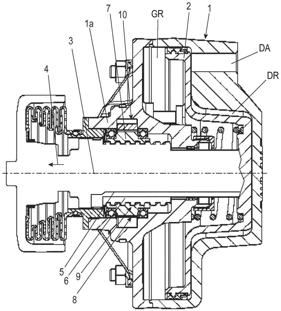
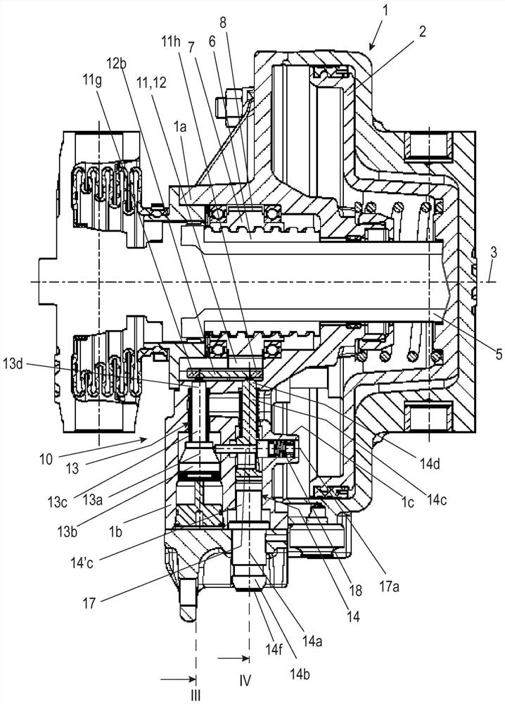
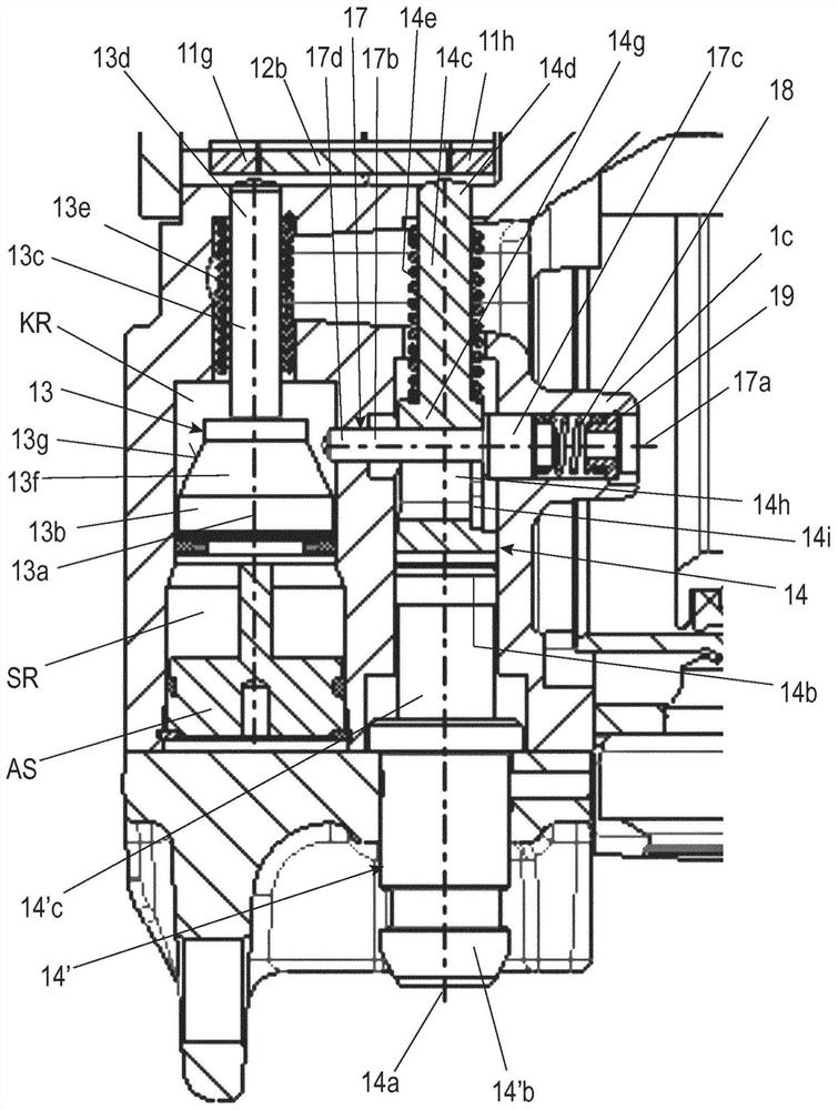
[0035] figure 1 A schematic longitudinal section through a first exemplary embodiment of a brake cylinder 1 according to the invention with a locking device 10 is shown. figure 2 The diagram in shows the basis of figure 1 A longitudinal section of the brake cylinder 1 rotated 90° around the piston axis 3 . Figure 2a Shown in rest position based on figure 2 An enlarged sectional view of the arrangement of the control piston 13 and the emergency release tappet 14 of the locking device 10 of the embodiment of FIG. Figure 2b The arrangement of the control piston 13 and the emergency release tappet 14 in the release position of the emergency release tappet 14 is shown. Figure 2c The released position of the control piston is shown.

[0036] The brake cylinder 1 has a locking device 10 as a mechanical brake force locking device and is provided for use in a rail vehicle.

[0037] The generally known construction and function of brake cylinder 1 will not be described in de...


PUM


Abstract

The invention relates to a brake cylinder (1) comprising a locking device (10) for mechanical brake force locking, in particular for rail vehicles, and comprising a service brake piston (2) which can be axially moved inside a housing (1), which can be moved by applying a pressure medium thereto, and which is coupled to a piston tube (5), said piston tube (5) being provided with a non-self-locking thread (9) which is engaged with a threaded nut (7) which is rotatably mounted in the housing (1), and the locking device (10) cooperating with toothing (8) of the threaded nut (7). The brake cylinder is designed such that the locking device (10) comprises one or more pawl(s) (11, 12), a control piston (13), an emergency release tappet (14), and a locking element (17) of the emergency release tappet (14).

Description

technical field [0001] The invention relates to a brake cylinder with a locking device for mechanical brake force locking according to the preamble of claim 1 . Background technique [0002] In order to prevent a parked rail vehicle from rolling away under any circumstances, the parking brake must ensure a correspondingly high braking force even without an external energy supply. [0003] If a rail vehicle parked in this way has to be towed, there is usually no compressed air supply available to the vehicle, via which the locking can be released. In this case, the parking brake must be equipped with a corresponding mechanical release (emergency release or auxiliary release), by means of which the parking brake can be released manually, ie without using external energy. The mechanical release is also used to safely disengage the pliers from force when changing brake linings. It is not permissible to change the brake linings while the spring accumulator is released pneumatic...

Claims


Application Information

Patent Timeline
Patent Type & Authority Applications(China)
IPC IPC(8): B60T13/36B60T17/16
CPCF16D2127/06F16D2127/04B60T17/16B60T13/365B61H13/04B60T13/38F16D2121/06
Inventor M-G·埃尔斯托尔普夫F·黑希特T·尼帕拉J·梅申伯格
Owner KNORR BREMSE SYST FUR SCHIENENFAHRZEUGE GMBH
Why Eureka
Try Eureka