

Substrate disposing device and method thereof
A technology for a substrate processing device and a substrate processing method, which is applied to devices, optics, instruments, etc. for coating liquid on the surface, can solve the problems of ripples on the liquid surface of the developer, time-consuming, tiny development spots, etc., and achieves suppression of development spots. Effect
Active Publication Date: 2010-08-25
TOKYO ELECTRON LTD
View PDF1 Cites 8 Cited by
- Summary
- Abstract
- Description
- Claims
- Application Information
AI Technical Summary
Problems solved by technology
However, in the case of such a structure, since the air blown from the blower 204 needs to be directed toward the upstream side of the transport path, the liquid surface of the developer D is rippled, and there is a possibility that the substrate G has minute development spots due to this. question
In addition, the developer D on the substrate can be efficiently removed by the air blown from the blower 204. However, similar to the structure of FIG. 6, as shown in FIG. The distance d in the direction becomes large, and it takes time until the rinse liquid S is supplied, so there is a problem that it causes development spots
Method used
View moreImage
Smart ImageViewing Examples

Examples
Embodiment Construction
Login to View More PUM
 Abstract
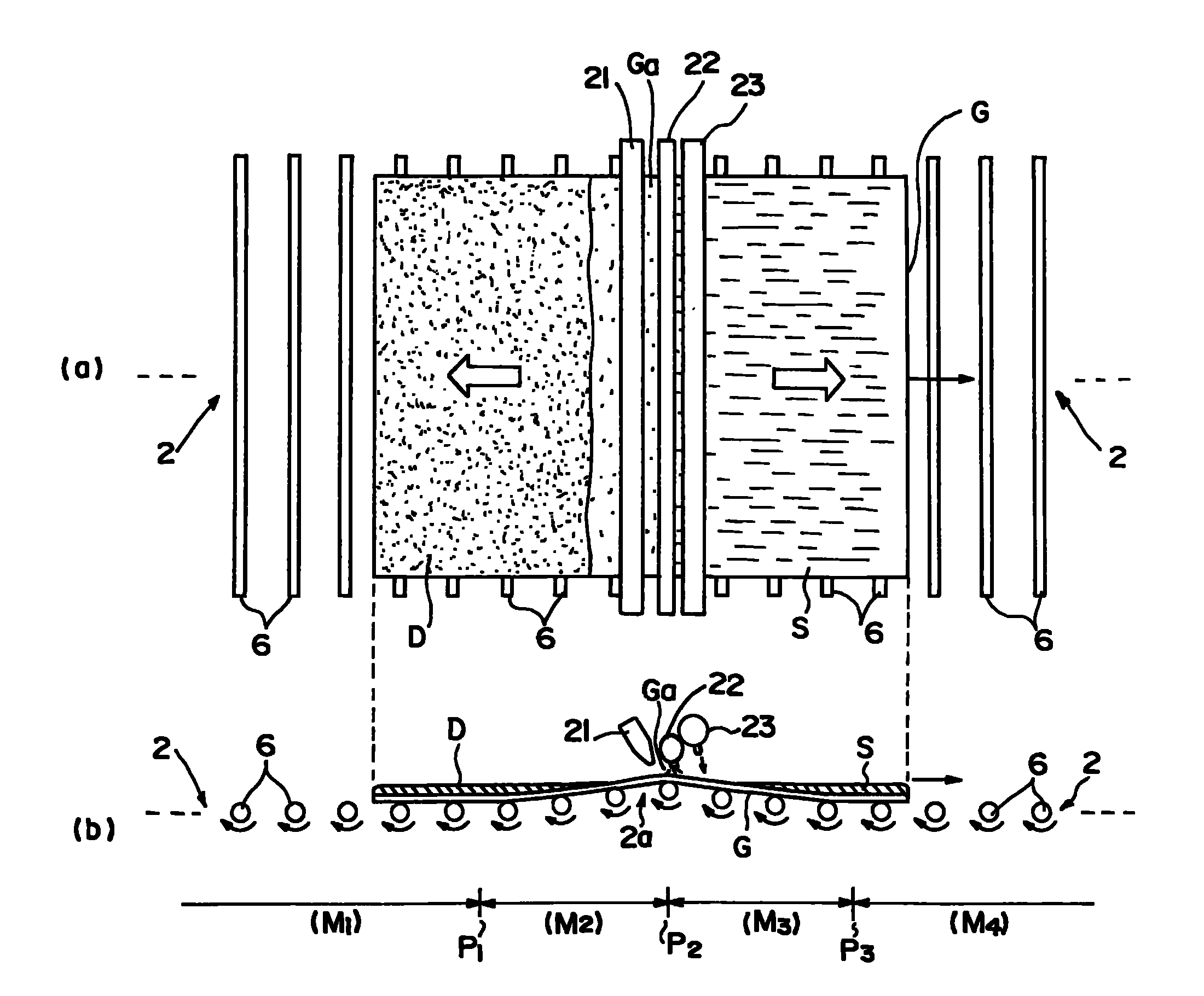
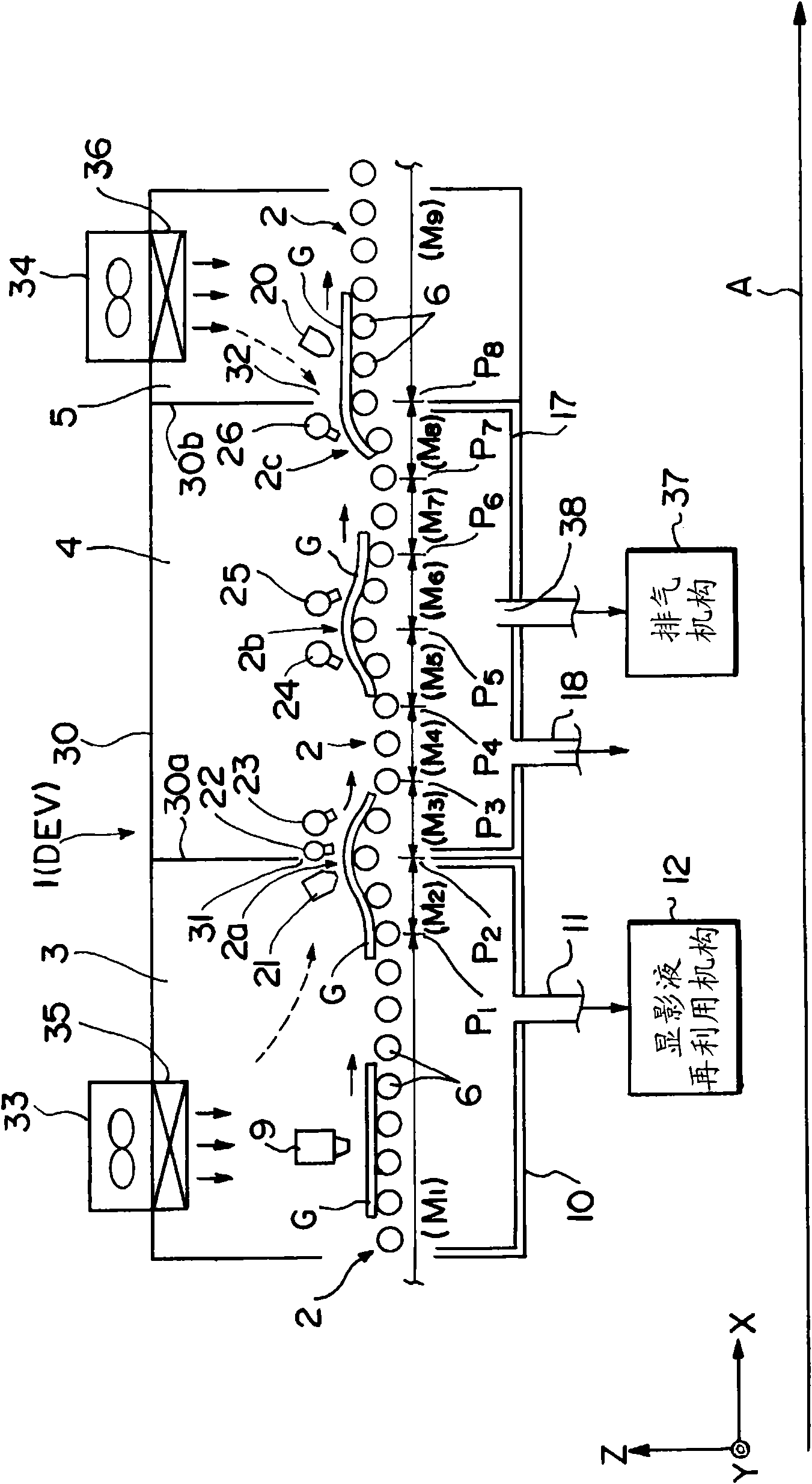
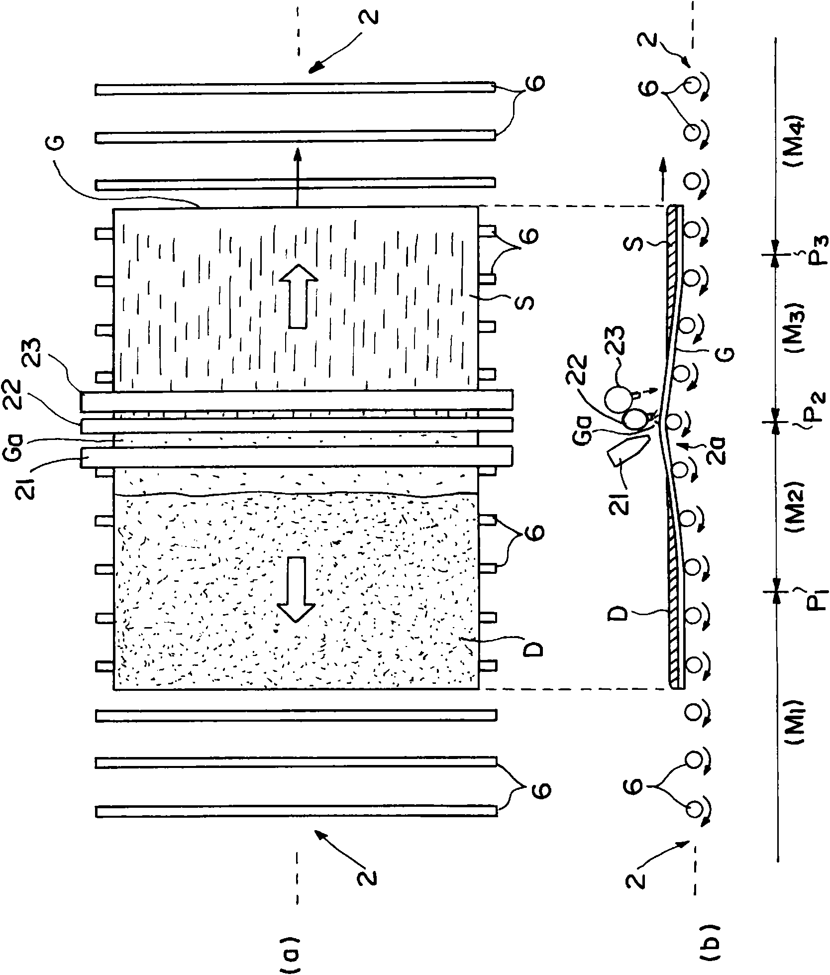
This invention provides a substrate disposing device and method thereof , including: a substrate transport path that transmits disposed substrate with a smooth gas flow; a first disposing liquid feed part which feeds disposing liquid to disposed substrate being delivered to the substrate transport path; gas supply part which blows certain gas flow to the disposed substrate supplied with first disposing liquid and delivered in the substrate transport path from the vertical direction to any directions of the delivery downstream; a first flush fluid supplying part which feeds a second disposing fluid at a certain speed to the surface of the disposed substrate being blown with gas flow from a gas flow supplying part and delivered in the substrate transport path; a second flush fluid supplying part which feeds a second disposing fluid at a higher speed than that of the first flush fluid to the surface of the disposed substrate being supplied with second disposing fluid and delivered in the substrate transport path.
Description
Substrate processing device and substrate processing method Technical field The present invention relates to a substrate processing technique for supplying a processing liquid on a substrate to be processed to perform predetermined processing, and more particularly, to a substrate processing apparatus and a substrate processing method that perform liquid processing while conveying the substrate in a horizontal direction in a flat flow manner. Background technique In recent years, in the resist coating and development processing system in LCD (liquid crystal display) manufacturing, as a development method that can advantageously cope with the increase in the size of LCD substrates (such as glass substrates), the The so-called advection method is a so-called advection method in which a series of development processes such as development, rinse, and drying are performed while conveying the substrate on the conveying path of the roller. Compared with the rotator method that rotate...
Claims
Login to View More Application Information
Patent Timeline
 Patent Type & AuthorityApplications(China)
IPC IPC(8): H01L21/00
CPCB05C11/1002B05D1/38G03F7/16G03F7/70933H01L21/67023H01L21/67028
Inventor藤原真树永田笃史佐田彻也
OwnerTOKYO ELECTRON LTD