Image forming device, powder supply device, and powder storage unit

a technology of image forming device and powder supply device, which is applied in the direction of optics, electrographic process apparatus, instruments, etc., can solve the problems of requiring useless time to stop the image formation operation, the operation of the image forming device is suspended temporarily, and the desired image concentration is no longer obtained, so as to shorten the operation stop time and reduce the exchange frequency of the toner storage unit

Active Publication Date: 2007-09-13
RICOH KK
View PDF24 Cites 9 Cited by
  • Summary
  • Abstract
  • Description
  • Claims
  • Application Information

AI Technical Summary

Benefits of technology

[0038] According to the embodiments of the invention, it is possible to reduce the exchange frequency of the toner storing unit and shorten the operation stop time substantially, without causing enlargement of the image forming device, and it is possible to provide an image forming device which can transport toner from the toner storing unit to the developing device smoothly.

Problems solved by technology

As a result, a desired image concentration is no longer obtained.
However, at the time of exchange of the toner supplying part, operation of the image forming device is suspended temporarily, and the useless time to stop the image formation operation is required for the exchange work and the restart of the image forming device.
However, when the toner storing unit having a large capacity for storing toner is used, the toner stored inside may be condensed, and there is a problem that it is difficult to smoothly transport the toner to the developing area.
However, in the method of Japanese Laid-Open Patent Application No. 2002-139902, the fluidity of the toner existing near the air exhaust outlet in the toner storing container is maintained, fully secured, but a sufficient amount of air is not supplied to the toner existing at the location distant from the air exhaust outlet.
Especially, when the capacity of the toner storing container is enlarged, it is difficult to keep good fluidity of the whole toner stored in the toner storing container over a long period of time.
However, the above-mentioned structure is attached to the developing device provided in the image forming device and the case in which the toner supplying part is installed in the developing device is included, and the space in which the developing part occupied in the image forming device becomes large, and enlargement and complication of the image forming device are not avoided.
However, in the case of the image forming device in which the toner collected by the cleaning device is transported to the toner storing unit or the developing device, it is likely to cause enlargement and complication of the image forming device.
If the image forming device is enlarged or complicated, the problem of the space for installation of the image forming device arises and the operability in the maintenance of exchange of the toner storing unit etc. gets worse.
And there is also a problem that the operation stop time of the image forming device is increased accompanied with the maintenance of the image forming device.
However, in the structure of Japanese Laid-Open Patent Application No. 04-198966, when the toner storing unit is installed outside the image forming device, the transport passage from the toner storing unit to the developing unit is usually excessively long.
If the transport passage of toner is excessively long, the toner may stagnate within the transport passage and a problem that the transporting speed of the toner be decreased may arise.
However, if the transport passage of toner is excessively long, it is difficult to perform the supply of toner while performing the toner amount adjustment accurately, and it will be difficult to perform the supply of toner appropriately.
That is, it will be difficult to carry out efficient and exact supply of toner from the toner storing unit to the developing device in the case of the structure of Japanese Laid-Open Patent Application No. 04-198966.
When a large-capacity toner storing unit is used, it is desired to install the toner storing unit at a location distant to some extent from the developing device, the same problem as in the above-mentioned case of the toner storing unit installed outside the image forming device will arise.

Method used


Image

  • Image forming device, powder supply device, and powder storage unit
  • Image forming device, powder supply device, and powder storage unit
  • Image forming device, powder supply device, and powder storage unit

Examples


Embodiment Construction

[0089] A description will be given of embodiments of the invention with reference to the accompanying drawings.

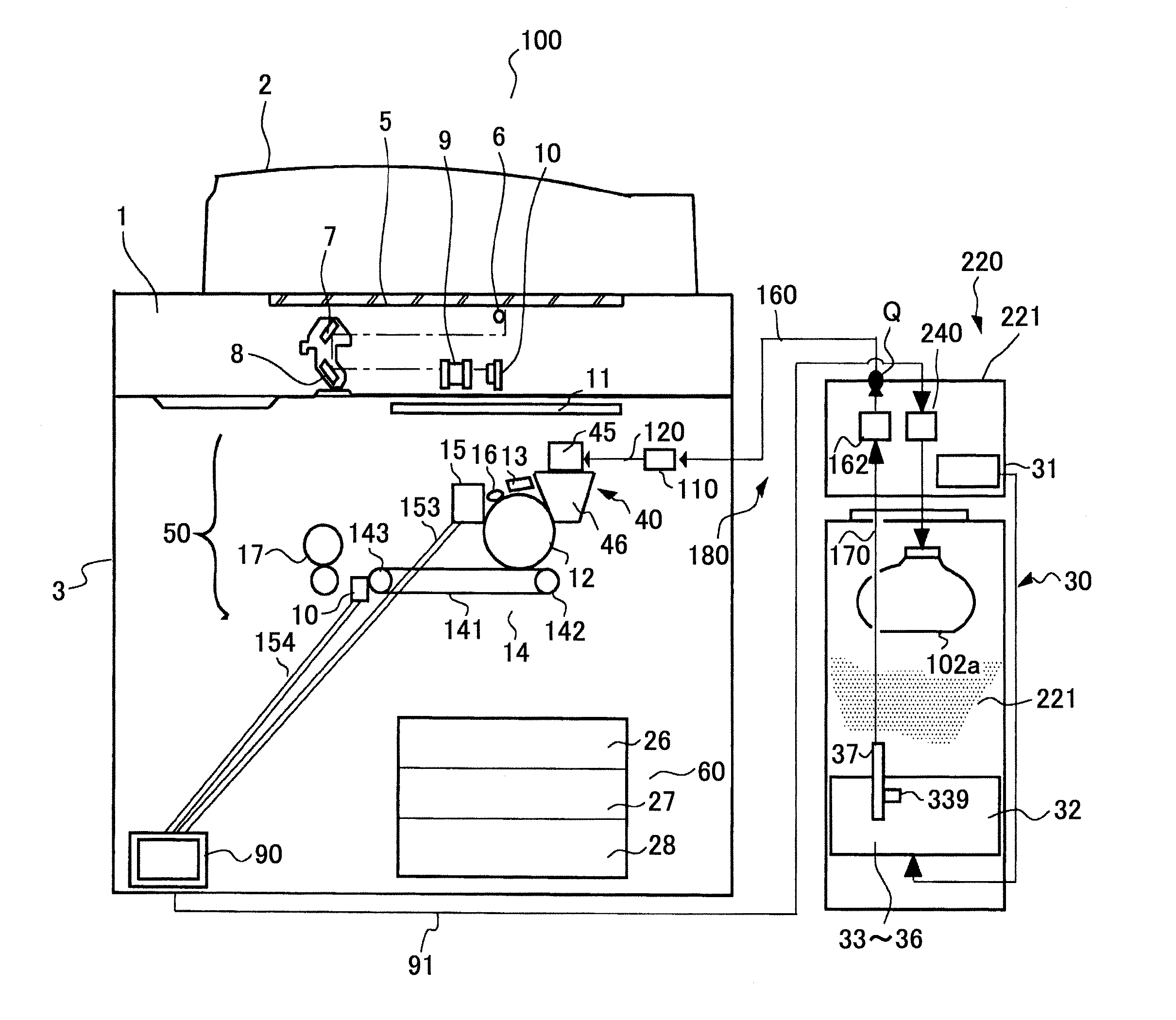
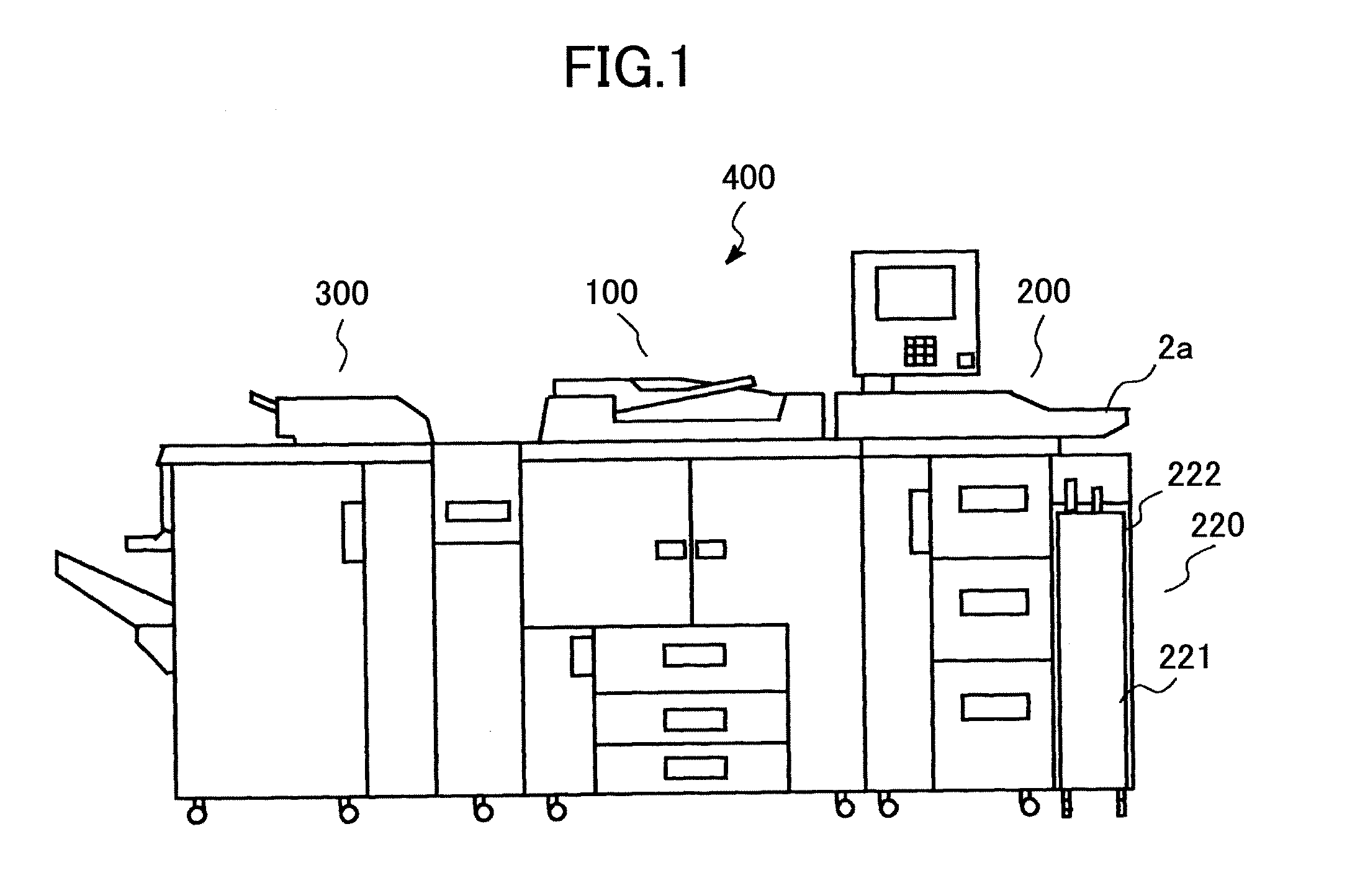
[0090]FIG. 1 is a schematic diagram showing the composition of an image forming device in an embodiment of the invention.

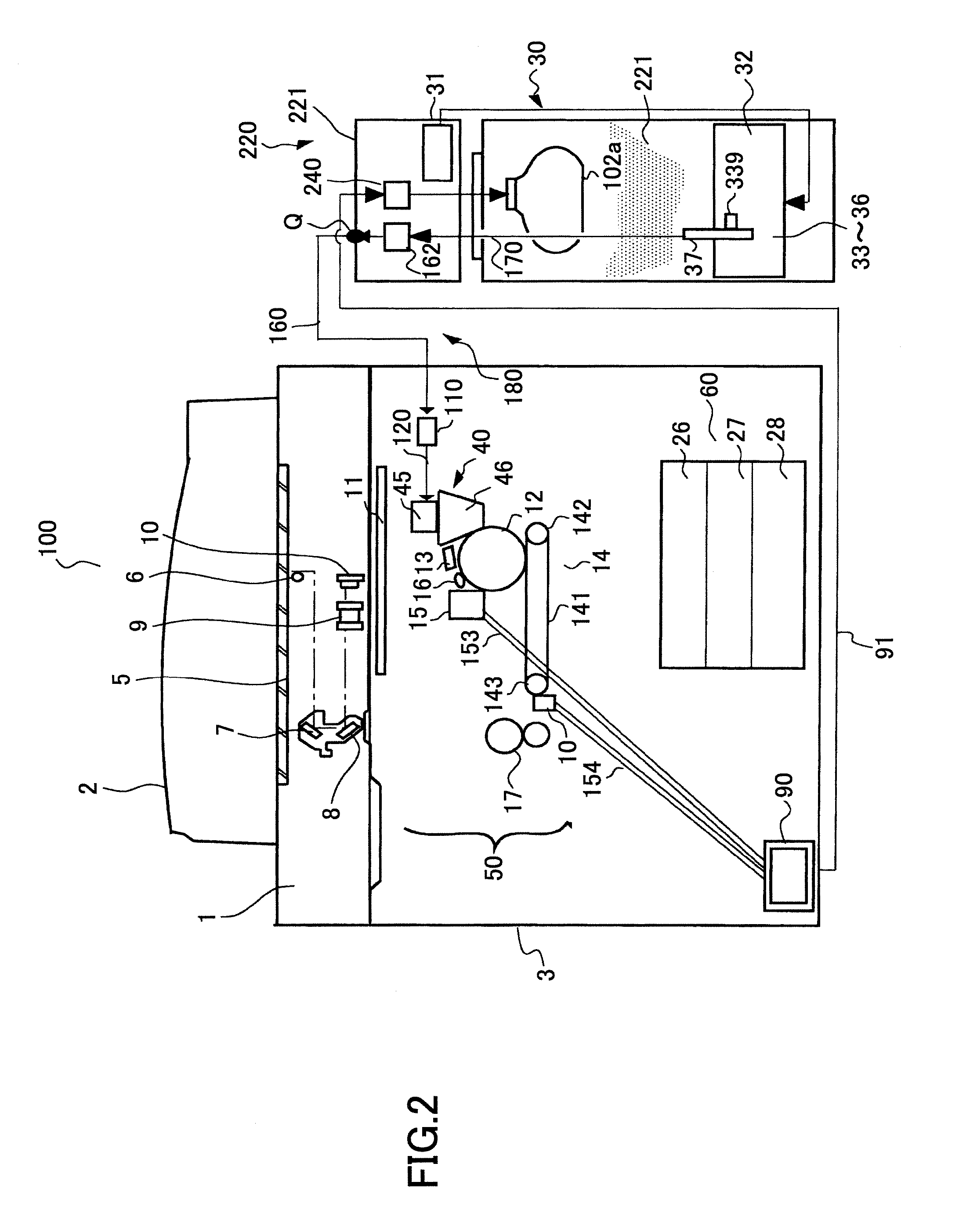
[0091] As shown in FIG. 1, an image-forming unit 100 is provided in the middle of an image formation system 400, and a sheet feeding unit 200 is provided on the right side of the image-forming unit 100. In this embodiment, the image-forming unit 100 is an image forming device using the electrophotographic printing method to form a fixed image using a toner. In the sheet feeding unit 200, a wing 2a is provided as a paper feed tray projecting from the right side, and a toner storing unit 220 which stores the toner used by the image-forming unit 100 is provided below the bottom of the wing 2a.

[0092] The toner storing unit 200 is connected with the image-forming unit 100 by the transport passage (not illustrated), and the toner stored in the toner storing ...


PUM


Abstract

In an image forming device including an image support object which supports an electrostatic latent image, and a developing device which turns the electrostatic latent image formed on the surface of the image support object, into a visible image with toner, a powder storing unit stores powder for image formation which is either a developing agent containing a toner and a carrier or a toner. A powder supplying unit supplies the powder stored in the powder storing unit, to the developing device. The powder storing unit includes a gas supplying unit which blows off a gas from an exhaust outlet of the gas supplying unit into the powder storing unit, and a powder passage which allows the powder storing unit to communicate with the developing device.

Description

BACKGROUND OF THE INVENTION [0001] 1. Field of the Invention [0002] This invention generally relates to an image forming device, such as a copier, a facsimile and a printer, and more particularly to an image forming device which is provided with a developing device for developing a latent image on an image support object, as well as with a powder storing unit for storing powder for image formation to be supplied to the developing device. [0003] 2. Description of the Related Art [0004] An electrophotographic printing system is one of image forming systems and many copiers, printers and facsimiles are provided as image forming devices using the electrophotographic printing system. [0005] In the electrophotographic printing system, an electrostatic latent image is formed by exposure of a uniformly charged surface of a photoconductor (which is an image support object) to optical writing, etc. This electrostatic latent image is visualized using either a toner of a two-component developin...

Claims


Application Information

Patent Timeline
Patent Type & Authority Applications(United States)
IPC IPC(8): G03G15/08
CPCG03G2215/066G03G2215/0802G03G15/0855G03G15/0879G03G15/0865G03G15/0875
Inventor ITOH, FUMIHITOAMANO, HIROSATOSUDO, KAZUHISA
Owner RICOH KK
Why Eureka
Try Eureka