Control device of rolling machine and control method thereof

A technology of a control device and a control method, which is applied to the rolling mill control device, metal rolling, metal rolling, etc., can solve the problems of large fluctuation and large time constant of the plate thickness change on the delivery side, and achieve the effect of suppressing the plate thickness fluctuation.

Active Publication Date: 2010-10-13
HITACHI LTD +1
View PDF6 Cites 28 Cited by
  • Summary
  • Abstract
  • Description
  • Claims
  • Application Information

AI Technical Summary

Problems solved by technology

Depending on the rolling conditions, the entry-side tension suppression system 27 performed by the entry-side TR2 may have a large time constant as described in Patent Document 3, and may cause large fluctuations in thickness fluctuations on the exit side.

Method used


Image

  • Control device of rolling machine and control method thereof
  • Control device of rolling machine and control method thereof
  • Control device of rolling machine and control method thereof

Examples


no. 1 Embodiment approach

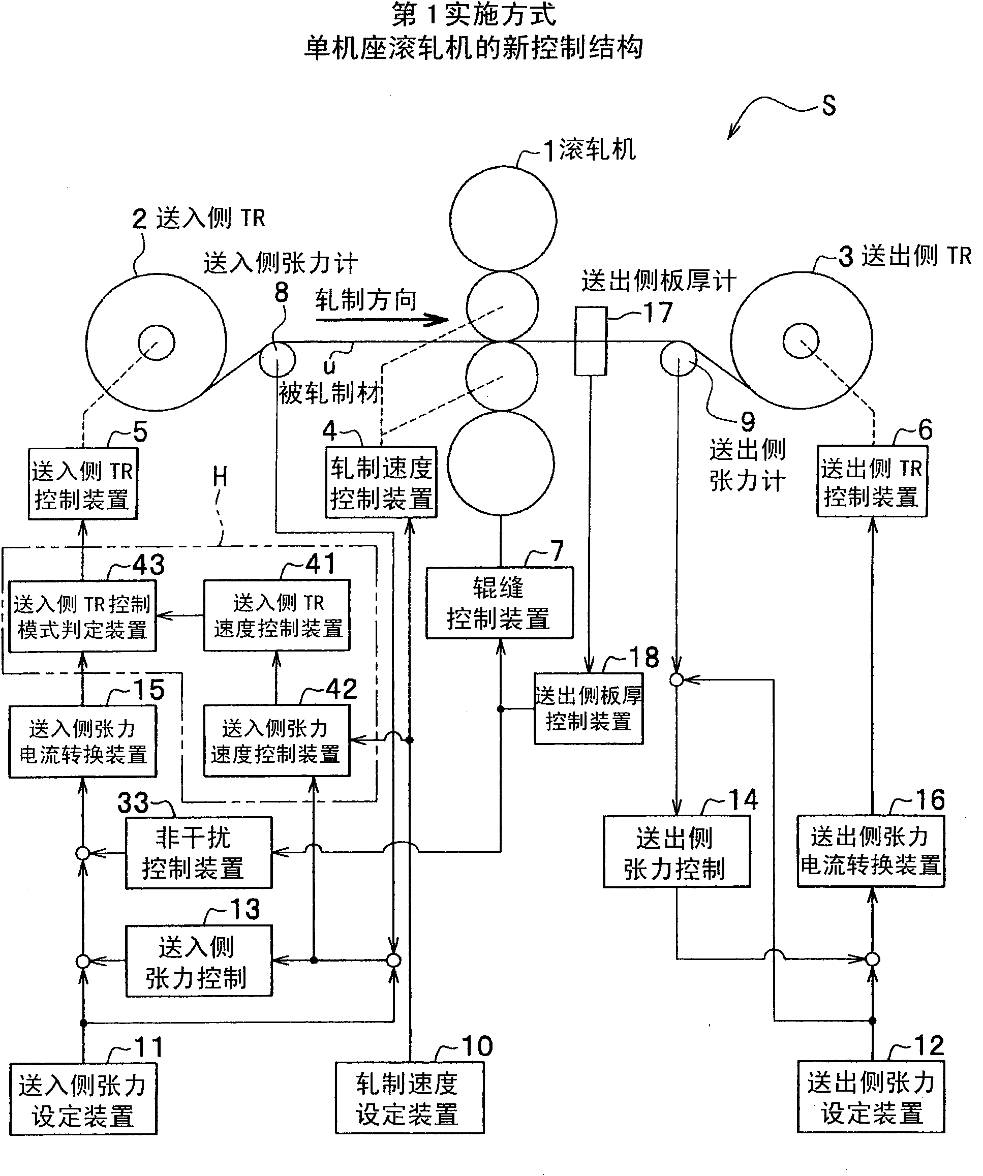
[0080] (Outline of Single Stand Rolling Mill S)

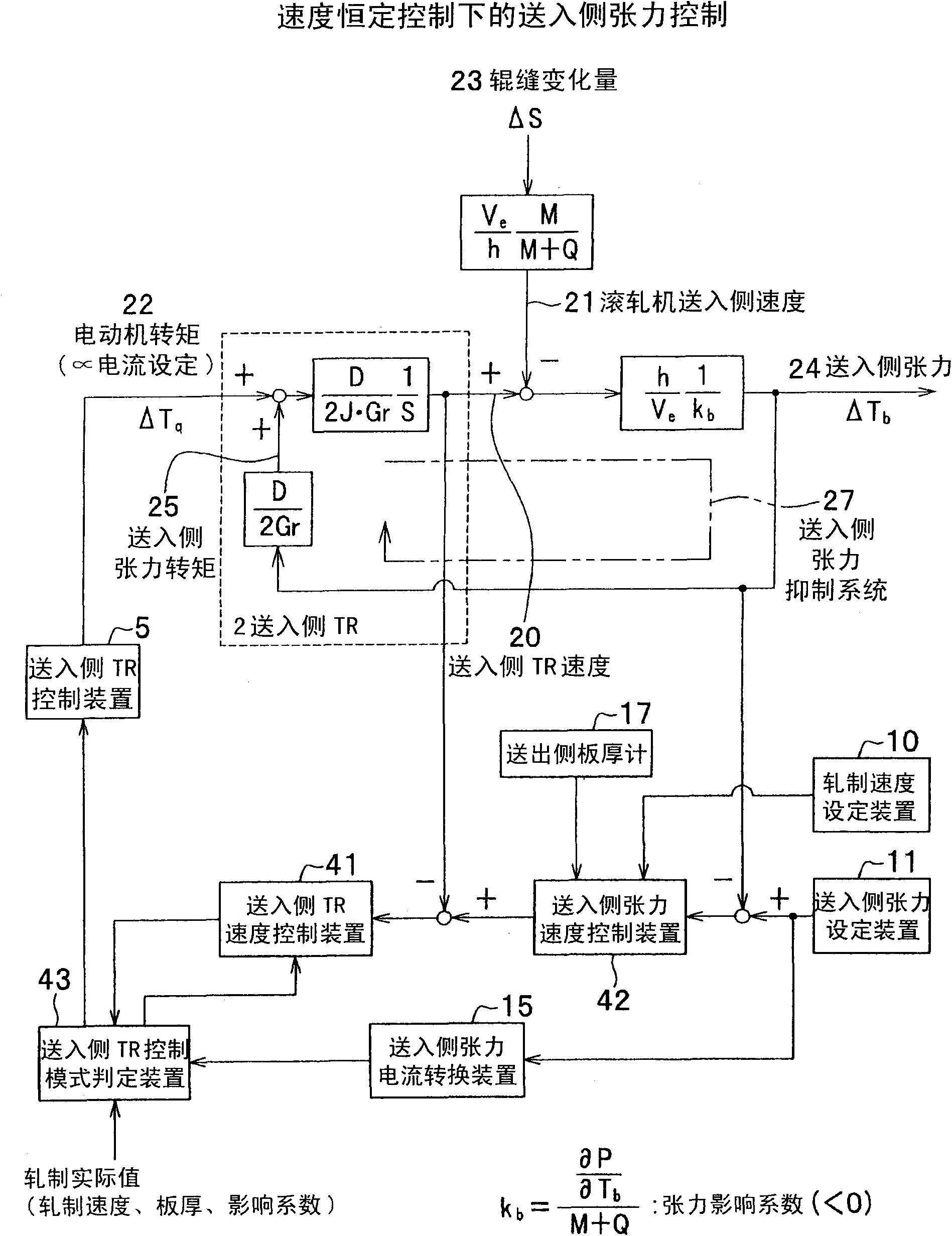
[0081] In the single-stand rolling mill S of the first embodiment, the tension reel on the sending side (hereinafter referred to as the sending side TR2) is controlled by constant speed control, and the rolling machine is controlled by the tension control with the speed of the tension reel as the control end. 1 The tension of the rolled material u on the feeding side is controlled. In this tension control, a dead band is provided in the tension deviation to be controlled to control the speed variation of the delivery side TR2 so as to minimize the thickness deviation of the delivery side of the rolled material u.

[0082] That is, the sending-side TR2 is controlled at a constant speed, and the speed of the sending-side TR2 is suppressed from fluctuating with tension fluctuations.

[0083] In addition, when the thickness variation (product thickness variation) of the delivery side of the rolled material u is large, the constant...

no. 2 Embodiment approach

[0132] Next, use Figure 6 A single-stand rolling mill according to a second embodiment will be described.

[0133] in addition, Figure 6 It is a diagram showing the control structure when the entry TR2 is controlled by the entry TR speed 20 in the single-stand rolling mill having no tensiometers on the entry side and the exit side of the rolling mill according to the second embodiment.

[0134] In the single-stand rolling mill of the second embodiment, the feeding-side / delivery-side tensiometers 8, 9 for measuring the actual tension are not provided on the feeding-in side and the sending-out side of the rolling mill 1 (refer to figure 1 )Case.

[0135] There is no tension meter for measuring the actual tension on the feed-in side and the send-out side of the single-stand rolling mill, such as Figure 6 As shown, because at the moment when the motor torque 22 is consistent with the tension torque 25 of the feeding side, the change of the TR speed 20 of the feeding side is...


PUM


Abstract

The present invention provides a control device of a rolling machine, which restrains the plate thickness variation of rolling machine generated by the speed variation of a tension reel at the feeding-in/feeding-out side. In the rolling machine, the feeding-in/feeding-out side of the rolling machine (1) is provided with the tension reel (2) for unreeling and reeling the rolled material (u). The control device is provided with a tension and speed control unit (41) which sustains the tension between the tension reel (2) and the rolling machine (1) to an expected value. On the other hand, for the derivation to a preset tension value in the preset range, the speed of the tension reel is fixed to a constant value without modifying the tension error for restricting the speed variation of the tension reel.

Description

technical field [0001] The present invention relates to a rolling mill, and more specifically relates to a rolling mill control device and a control method thereof for controlling a tension reel for uncoiling and winding up a rolled material. Background technique [0002] Figure 7 It is a schematic diagram which shows the control structure of the single stand (single stand) rolling mill S100 as an example of the conventional rolling mill. [0003] Single stand rolling mill S100, relative to the rolling direction of rolling mill 1 ( Figure 7 , indicated by the arrow symbol), there is a feed-in side tension reel (hereinafter referred to as feed-in side TR2) on the feed-in side of the rolling mill 1 that unrolls the rolled material u (hereinafter referred to as the feed-in side TR2), and there is a pair of rolling mill 1 on the feed-out side. The sending-side tension reel (hereinafter referred to as sending-side TR3 ) on which the rolled material u is curled. [0004] The se...

Claims


Application Information

Patent Timeline
Patent Type & Authority Applications(China)
IPC IPC(8): B21B37/00B21B37/48
CPCB21B37/54
Inventor 服部哲福地裕加贺慎一斋藤武彦
Owner HITACHI LTD
Why Eureka
Try Eureka