Electric connector

A technology of electrical connectors and connecting parts, which is applied in the direction of protective grounding/shielding devices of connecting parts, can solve the problems of poor shielding effect of electrical connectors, etc., and achieve the effect of good signal shielding effect.

Inactive Publication Date: 2010-10-13
芜湖德仓光电有限公司
View PDF1 Cites 3 Cited by
  • Summary
  • Abstract
  • Description
  • Claims
  • Application Information

AI Technical Summary

Problems solved by technology

[0003] In order to solve the technical problem of poor shielding effect of electrical connectors in the prior art, it is necessary to provide an electrical connector with better signal shielding effect

Method used


Image

  • Electric connector
  • Electric connector
  • Electric connector

Examples


Embodiment Construction

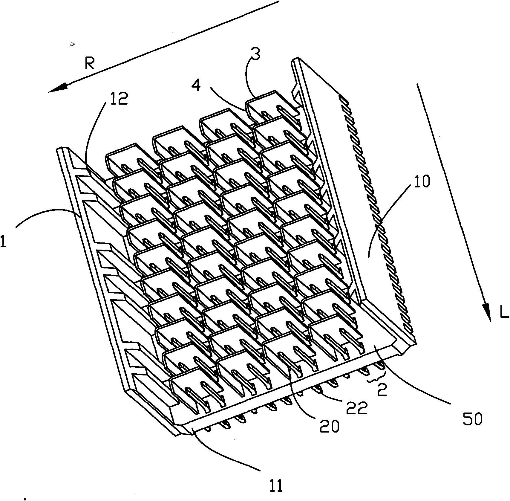
[0012] see figure 1 , figure 1 It is a perspective view of an electrical connector in a preferred embodiment of the present invention. The electrical connector includes a base 1, a plurality of differential signal pairs 2 accommodated in the base 1, and a plurality of differential signal pairs 2 in the column direction L. First shielding members 3 arranged at intervals and a plurality of second shielding members 4 arranged at intervals from the differential signal pairs 2 in the row direction R. The first shielding member 3 is used to shield the signal crosstalk between the differential signal pairs 2 in adjacent rows, and the second shielding member 4 is used to shield the signal crosstalk between the differential signal pairs 2 in adjacent columns.

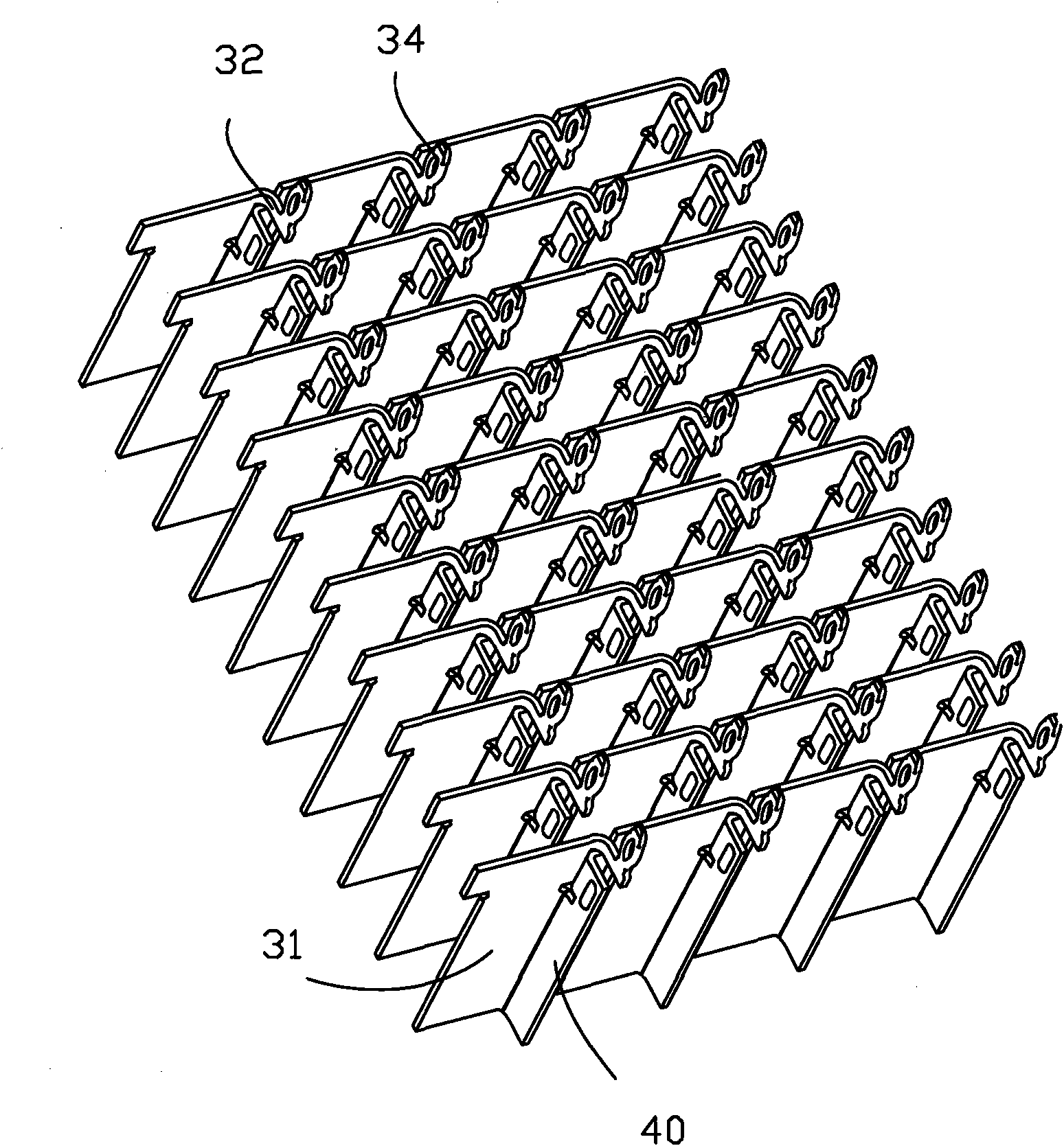
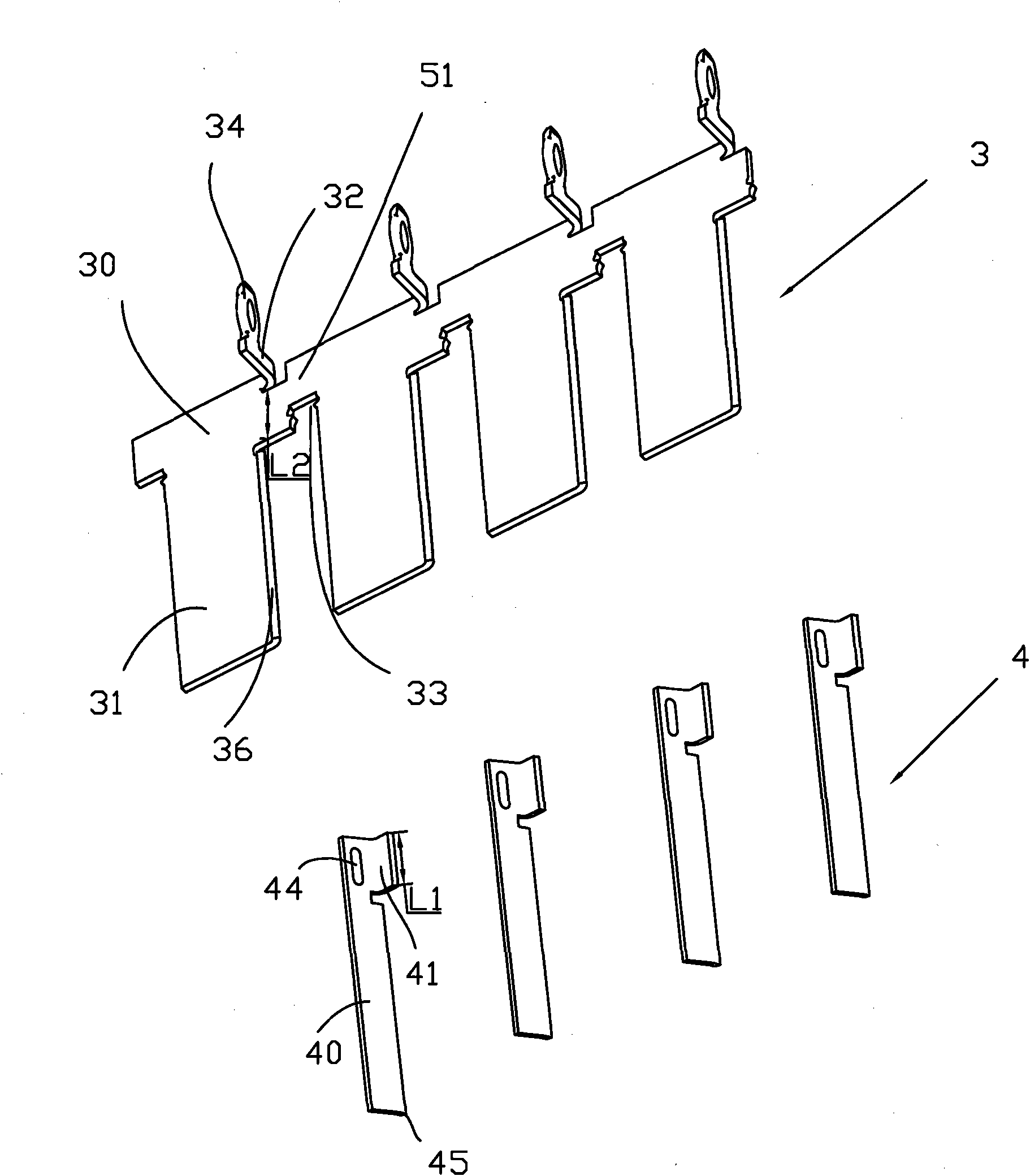
[0013] Please also refer to figure 2 and image 3 , figure 2 yes figure 1 A perspective view of the first and second shielding members 3, 4 from an angle of the electrical connector shown, image 3 yes figure 2 An expl...


PUM


Abstract

The invention relates to an electric connector which comprises a base, a plurality of differential signal pairs, a plurality of first shielding members and a plurality of second shielding members, wherein the differential signal pairs, the first shielding members and the second shielding members are contained in the base, and the differential signal pairs and the first shielding members are alternately arranged in the first direction; the second shielding members and the differential signal pairs are alternately arranged in the second direction which is perpendicular to the first direction; and each second shielding member comprises a contact part which contacts the first shielding member. The first shielding members and the second shielding members can shield signal cross-disturbance between adjacent differential signal pairs in two directions; and thus, better signal shielding effect can be achieved.

Description

【Technical field】 [0001] The invention relates to an electrical connector, especially an electrical connector with a shielding member. 【Background technique】 [0002] An existing electrical connector generally includes a plurality of differential signal pairs for transmitting differential signals and a plurality of shielding sheets, and a good shielding effect is achieved by arranging shielding members between adjacent differential signal pairs. An existing electrical connector includes a plurality of shielding sheets located between differential signal pairs in adjacent rows. However, this shielding sheet can only block the signal crosstalk between the differential signal pairs in adjacent rows, but cannot block the crosstalk between the differential signal pairs in adjacent columns, so the signal shielding effect is poor. 【Content of invention】 [0003] In order to solve the technical problem of poor shielding effect of the electrical connector in the prior art, it is n...

Claims


Application Information

Patent Timeline
Patent Type & Authority Applications(China)
IPC IPC(8): H01R13/648
Inventor 张大玉刘萌
Owner 芜湖德仓光电有限公司
Why Eureka
Try Eureka