Novel structure for connecting ball screw and worm gear

A connecting mechanism and turbine technology, applied in the field of presses, can solve the problems of easy gnawing of positioning pins, abnormal wear of moving parts, easy blocking of positioning pins, etc., so as to prolong the service life and avoid abnormal wear and tear. stuck effect

Inactive Publication Date: 2010-10-20
尹克善
View PDF0 Cites 3 Cited by
  • Summary
  • Abstract
  • Description
  • Claims
  • Application Information

AI Technical Summary

Problems solved by technology

[0004] The purpose of the present invention is to provide a new type of connection mechanism between the ball screw and the turbine, which overcomes the adjustment problem caused by the positioning pin being easily stuck in the gap in the existing connection mechanism between the ball screw and the turbine. Difficult defects; at the same time, in order to overcome the existing mechanism, the edges and corners of the positioning pin are easy to gnaw off the material on the turbine that is in contact with it, and the resulting broken nitrate falls between the ball head and the ball bowl, causing movement Defects of abnormal wear between components

Method used


Image

  • Novel structure for connecting ball screw and worm gear
  • Novel structure for connecting ball screw and worm gear
  • Novel structure for connecting ball screw and worm gear

Examples


Embodiment Construction

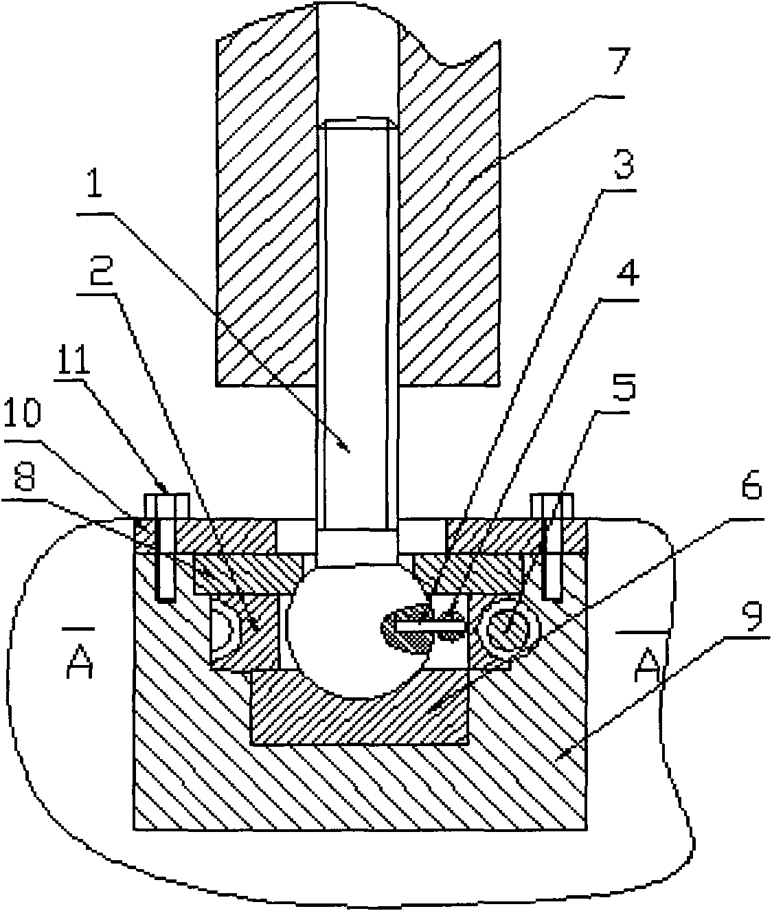
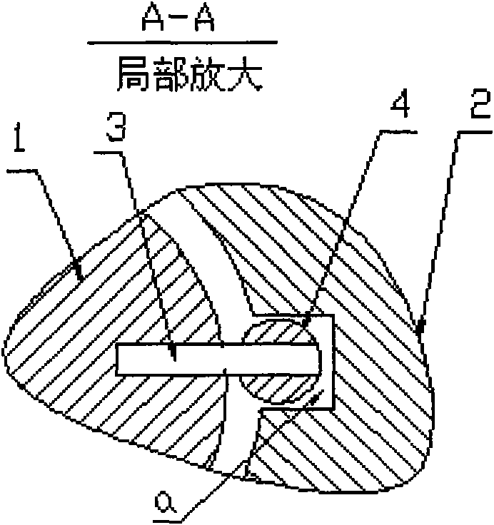
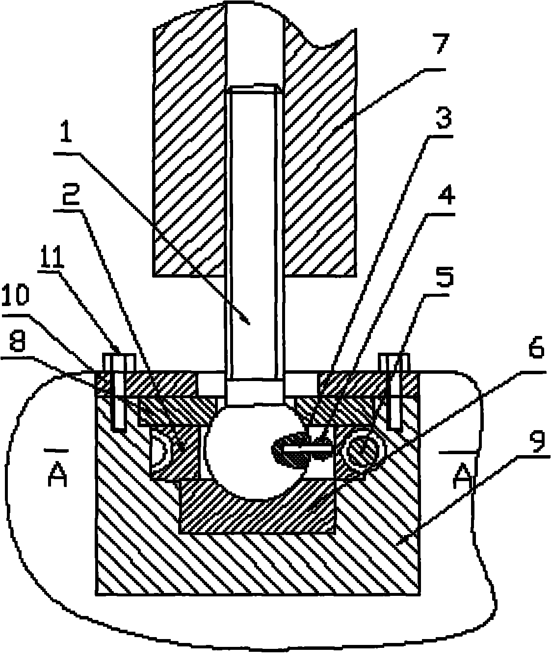
[0010] Install the lower ball bowl (6) to the bottom of the turbine case (9), install the worm rod (5) to the correct position of the turbine case (9), and place the turbine ( 2) Correct installation, to ensure that the worm gear (2) and the worm rod (5) are properly meshed, install the positioning pin (3) into the blind hole of the spherical part of the ball screw (1), and at the same time place the positioning pin on the protruding ball part (3) Install the upper joint ball (4), align the joint ball (4) with the notch on the turbine (2), pass the ball of the ball joint screw (1) through the middle hole of the turbine (2) and install At the ball bowl part of the lower ball bowl (6), pass the upper ball bowl (8) through the upper part of the ball screw (1), and install it correctly on the top of the turbine case (9), and put the gland plate (10 ) is installed on the turbine casing (9) and fixed with bolts (11) at the same time. Finally, install the connecting rod (7) on top o...


PUM


Abstract

The invention discloses a novel structure for connecting a ball screw and a worm gear, which connects the ball screw and the worm gear in a way that: a lower ball cup is arranged at the bottom of a worm gear case; a worm is arranged at a proper position on the worm gear case; the worm gear is correctly arranged in a cavity of the worm gear case in a way that the worm gear is ensured to be correctly meshed with the worm; a positioning pin is arranged in a blind hole of a ball part of the ball screw; simultaneously an upper joint ball body is arranged on the positioning pin on the protruded ball part, and is aligned with a nick on the worm gear; the ball part of the ball screw passes through a centre hole of the worm gear to be arranged on a ball cup part of the lower ball cup; an upper ball cup passes through the upper part of the ball screw and is correctly arranged on the worm gear case; a pressure cover plate is arranged on the worm gear case and is simultaneously fixed by bolts; and finally a connecting rod is arranged on the ball screw.

Description

technical field [0001] The invention relates to a connection mechanism between a ball screw and a turbine, in particular to a novel connection mechanism between a ball screw and a turbine. It belongs to the technical field of presses. Background technique [0002] At present, in some medium, large and high-end press products, the closed height adjustment of the slider adopts the method of motorized adjustment, that is, the worm rod driven by the motor is used, the worm rod drives the turbine, and the turbine drives the ball screw in the continuous The internal thread of the rod is rotated to adjust the closing height of the slider. In the above-mentioned mechanism connection, a hole perpendicular to the axis of the ball screw is drilled on the ball head, and a positioning pin is installed in the hole. There is a notch on the edge of the inner hole of the turbine, and the protruding part of the positioning pin is stuck in the notch, so as to limit the mutual rotation between...

Claims


Application Information

Patent Timeline
Patent Type & Authority Applications(China)
IPC IPC(8): B30B15/00F16H1/16
Inventor 尹克善
Owner 尹克善
Why Eureka
Try Eureka