Elevator auxiliary escape device

An escape device, elevator technology, applied in elevators, transportation and packaging, elevators and other directions in buildings, which can solve problems such as fear, stopping between two floors, and inconvenient rescue and escape.

Inactive Publication Date: 2012-07-18
XIAMEN A L B T MACHINE EQUIP
View PDF0 Cites 0 Cited by
  • Summary
  • Abstract
  • Description
  • Claims
  • Application Information

AI Technical Summary

Problems solved by technology

[0003] However, although this elevator equipment can achieve the expected effect of being convenient for users to arrive at the floor they want to go to, it is also found in its actual operation that when various factors such as power outages or malfunctions occur, the elevator equipment will When the power is lost and the elevator car cannot be moved, the elevator car in operation will stop immediately and will not go up and down again to prevent dangerous situations from happening. However, this design also causes the elevator car to stop between the two floors, not only It is extremely inconvenient to rescue and get out of trouble, and sometimes limited by the place where the elevator equipment is installed, it is impossible to forcibly pry open the elevator door for rescue. At this time, the users in the elevator car can only wait for the power supply to be restored or failure After exclusion, let the elevator car really stop in front of the elevator doors on each floor before opening the elevator door and the door of the elevator car to allow the user to leave and get out of trouble. In addition to causing a waste of user waiting time during the waiting period, it will also It causes psychological fear, so that there is still room for improvement in the overall implementation and use of the elevator equipment

Method used


Image

  • Elevator auxiliary escape device
  • Elevator auxiliary escape device
  • Elevator auxiliary escape device

Examples


Embodiment Construction

[0026] In order to have a more complete and clear disclosure of the technical content, creation purpose and achieved effects of the present invention, the detailed description is given below, and please also refer to the disclosed drawings and figure numbers:

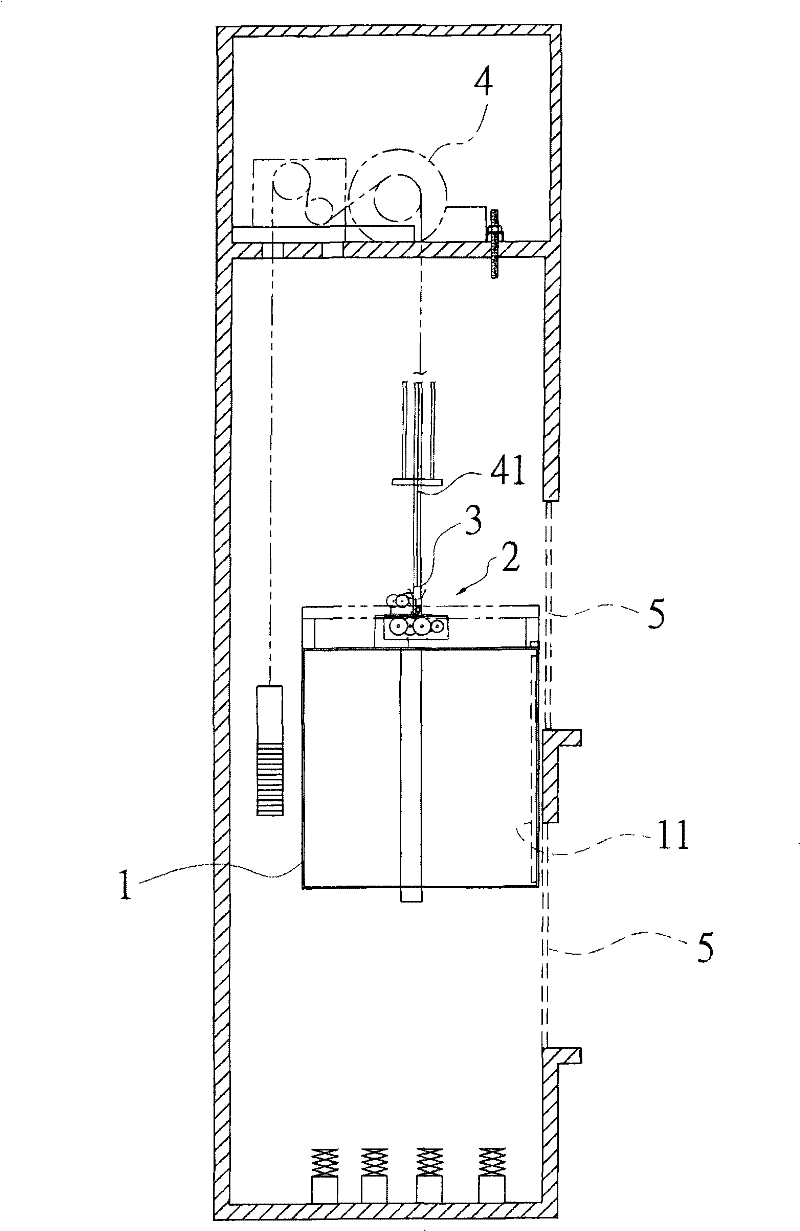
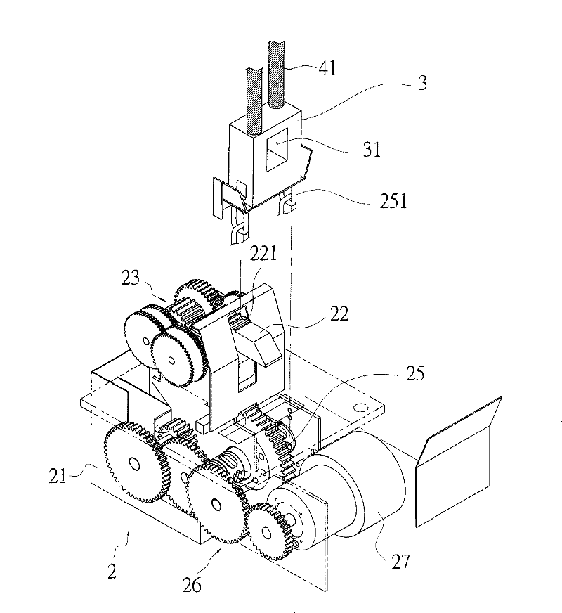
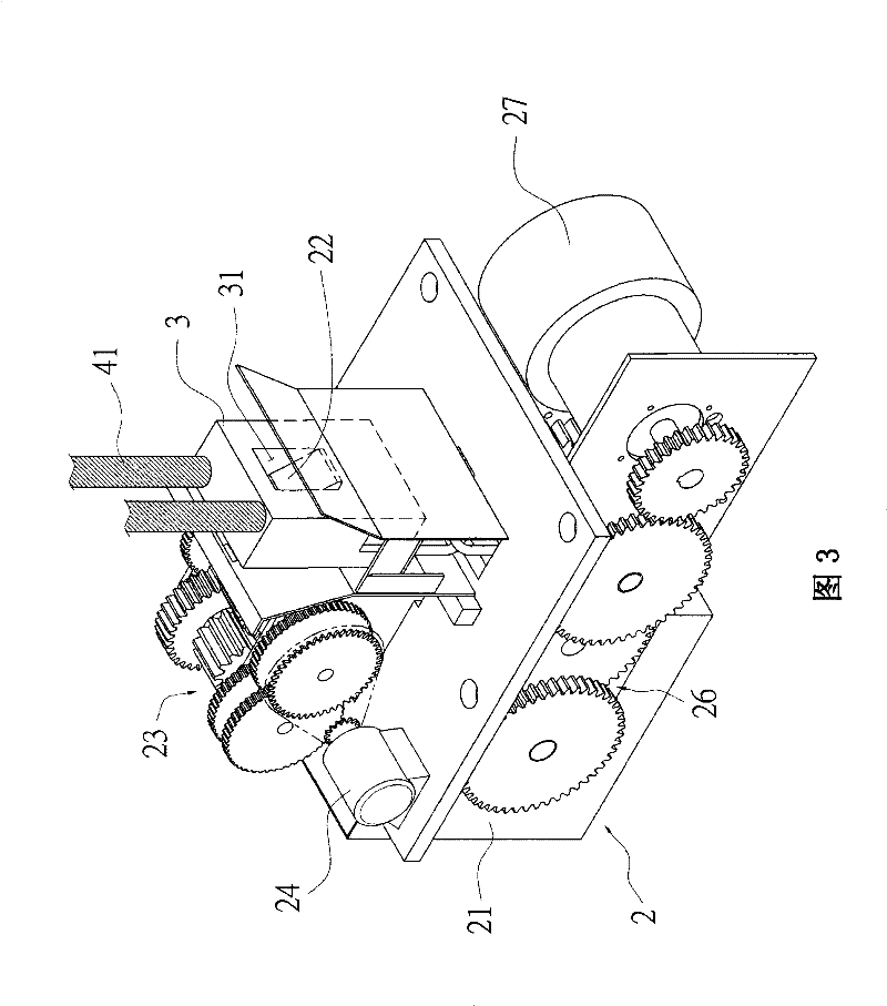
[0027] First, see figure 2 As shown in the schematic diagram of the overall structure of the present invention, the present invention is mainly fixed with an auxiliary escape device 2 on the top of the elevator car 1, and a support block 3 is provided corresponding to the auxiliary escape device 2, and the upper end of the support block 3 is connected by a steel cable 41 Fixed, the other end of the steel cable 41 is wound on the elevator power source 4, and an elevator door 5 is provided on each floor corresponding to the door 11 of the elevator car 1; please refer to figure 2 Three-dimensional exploded view of the present invention, image 3 Combination perspective view of the present invention and Figure 4 Shown ...


PUM


Abstract

The invention relates to an elevator auxiliary escape device, a frame body of which is fixedly connected to the top end of an elevator car, the upper end of the frame body is pivoted with a clamping block positioned and supported by a clamping block speed-reducing gear set, the clamping block speed-reducing gear set is driven by a clamping block power source, the lower end of the frame body is pivoted with a winding wheel supported and positioned by a winding wheel speed-reducing gear set, the winding wheel is provided with a connecting member in a winding way, the winding wheel speed-reducing gear set is driven by a winding wheel power source, a supporting block is additionally provided, the upper end of the supporting block is fixedly connected by a steel cable, the supporting block is provided with a clamping hole for clamping and fixing the clamping block, and the supporting block is used for connecting and fixing the connecting member wound on the winding wheel. Therefore, the invention can ensure that an elevator stops on an elevator door at the closest floor to enable people taking the elevator to smoothly escape when losing power not to act because of factors of power failure, faults and the like, and can be convenient for controlling the elevator to be lifted or restored or positioned so as to increase the practicability on the integral application.

Description

technical field [0001] The present invention relates to an elevator auxiliary escape device, in particular to an elevator door position that can not only make the elevator descend and stop at the nearest floor when the elevator loses its power due to power failure, failure and other factors. , so that people who take the elevator can escape smoothly, and it is also an elevator auxiliary escape device that can be convenient for controlling the elevator to rise and return to the positioning. Background technique [0002] In today's society, due to the narrowness of the land and the dense population, various buildings are generally built higher and higher with more and more floors. Therefore, in order to allow people to easily go up and down the floors and reach the floors they want to go, it is necessary to use them in buildings. Elevator equipment is generally installed; and the common elevator equipment is mainly equipped with several cable pulleys on the top of the elevator...

Claims


Application Information

Patent Timeline
Patent Type & Authority Patents(China)
IPC IPC(8): B66B5/26B66B11/00
Inventor 陈永欣
Owner XIAMEN A L B T MACHINE EQUIP
Why Eureka
Try Eureka