
New compression valve assembly

A compression valve and assembly technology, applied in the direction of springs, shock absorbers, spring/shock absorbers, etc., can solve the problem of loss of shock absorption effect of the shock absorber, plastic deformation of the compression valve plate, permanent failure of the compression valve assembly, etc. problems, to achieve the effect of improving the ability to resist accidental impact deformation, improving service life and safety factor

Inactive Publication Date: 2010-11-24
ZHEJIANG WANXIANG SYST +1
View PDF4 Cites 0 Cited by
  • Summary
  • Abstract
  • Description
  • Claims
  • Application Information

AI Technical Summary

Problems solved by technology

For compression valves with pure valve plate structure, when the assembly is subjected to occasional large impacts, the plastic deformation or fracture of the compression valve plate often occurs, which leads to permanent failure of the compression valve assembly and the shock absorber loses its shock absorption effect

Method used


Image

  • New compression valve assembly
  • New compression valve assembly
  • New compression valve assembly

Examples


Embodiment

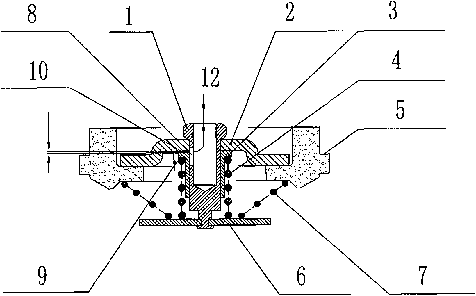
[0014] Example: such as figure 1 , this new type of compression valve assembly has a compression valve seat 5 on the outside, a valve core 1 inside, and the outer side of the limit ring 2 sleeved on the valve core 1 is fixed on the compression valve seat 5, and the valve core 1 is covered with a A sliding fit compression valve body 3 is formed, the upper part of the compression valve body 3 extends to form a valve body base 9, the bottom of the valve core 1 is equipped with a limit plate 6, one end of the compression spring 4 is fixed on the valve body base 9, and the other end is fixed on the valve body base 9. On the limiting piece 6 , under the action of the compression spring 4 , the compression valve body 3 is offset against the limiting ring 2 through the valve body base 9 . When the compression valve body 3 moves relative to the valve core 1, a compression orifice 10 is formed between the valve body base 9 and the limit ring 2, the inside of the valve core 1 is hollow,...


PUM


Abstract

The invention relates to a new compression valve assembly. The compression valve assembly comprises a valve core, a compression valve body and a compression valve seat, wherein an outer side of a spacing collar which is sleeved on the valve core is fixed on the compression valve seat; the compression valve body which is in sliding fit with the valve core is sleeved outside the valve core; the compression valve body is provided with a valve body base which is formed by extending; a compression spring of which one end is fixed on the valve body base is arranged outside the compression valve body; the compression valve body is pressed against the spacing collar under the action of the compression spring; a compression throttle orifice is formed between the compression valve body and the spacing collar when the compression valve body slides; and the valve core is hollow, and the outer wall of the valve core is provided with a valve core path which is communicated with the inner part of the valve core and the compression throttle orifice. The compression valve assembly has the advantages that: the accidental shock deformation resistance of the shock absorber compression valve assembly is improved, so when the compression valve body is subjected to large hydraulic shock, the compression valve body cannot generate permanent plastic deformation so as to prolong the use life and improve the security coefficient of a product.

Description

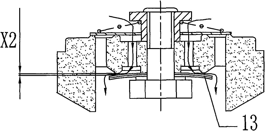
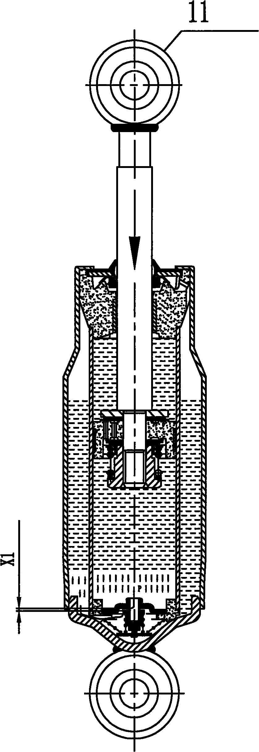
technical field [0001] The invention relates to a shock absorber accessory, in particular to a novel compression valve assembly. Background technique [0002] For a long time, the compression valve assembly of the shock absorber has generally adopted a pure valve plate throttling structure, and the compression damping force of the shock absorber is realized by forming a throttling gap X2 after the compression valve plate is deformed when it is subjected to oil pressure, such as figure 2 , 4 . For the compression valve with pure valve plate structure, when the assembly is subjected to accidental and large impacts, the plastic deformation or fracture of the compression valve plate often occurs, which leads to permanent failure of the compression valve assembly and the shock absorber loses its shock absorption effect. Contents of the invention [0003] The present invention solves the above-mentioned shortcomings of the prior art and provides a novel compression valve assem...

Claims


Application Information

Patent Timeline
IPC IPC(8): F16F9/34
Inventor 朱荣
Owner ZHEJIANG WANXIANG SYST
Learn More