
Novel compression damping control valve

A technology of damping control and compression valve, which is applied in the direction of spring, shock absorber, spring/shock absorber, etc. It can solve the problems of plastic deformation of compression valve plate, permanent failure and fracture of compression valve assembly, and improve service life And the safety factor, the effect of ensuring the ability to resist accidental impact deformation

Inactive Publication Date: 2010-10-06
ZHEJIANG WANXIANG SYST +1
View PDF7 Cites 1 Cited by
  • Summary
  • Abstract
  • Description
  • Claims
  • Application Information

AI Technical Summary

Problems solved by technology

In practice, we found that when the compression valve assembly with pure valve plate structure is subjected to occasional and unexpected large impacts, the plastic deformation or fracture of the compression valve plate often occurs, which leads to permanent failure of the compression valve assembly and loss of the shock absorber. shock absorption effect

Method used


Image

  • Novel compression damping control valve
  • Novel compression damping control valve
  • Novel compression damping control valve

Examples


Embodiment Construction

[0015] The present invention will be further described below in conjunction with the accompanying drawings and embodiments. While the invention will be described in conjunction with the preferred embodiments, it will be understood that it is not intended to limit the invention to the described embodiments. On the contrary, the invention is to cover alternatives, modifications and equivalents, which may be included within the scope of the invention as defined by the appended claims.

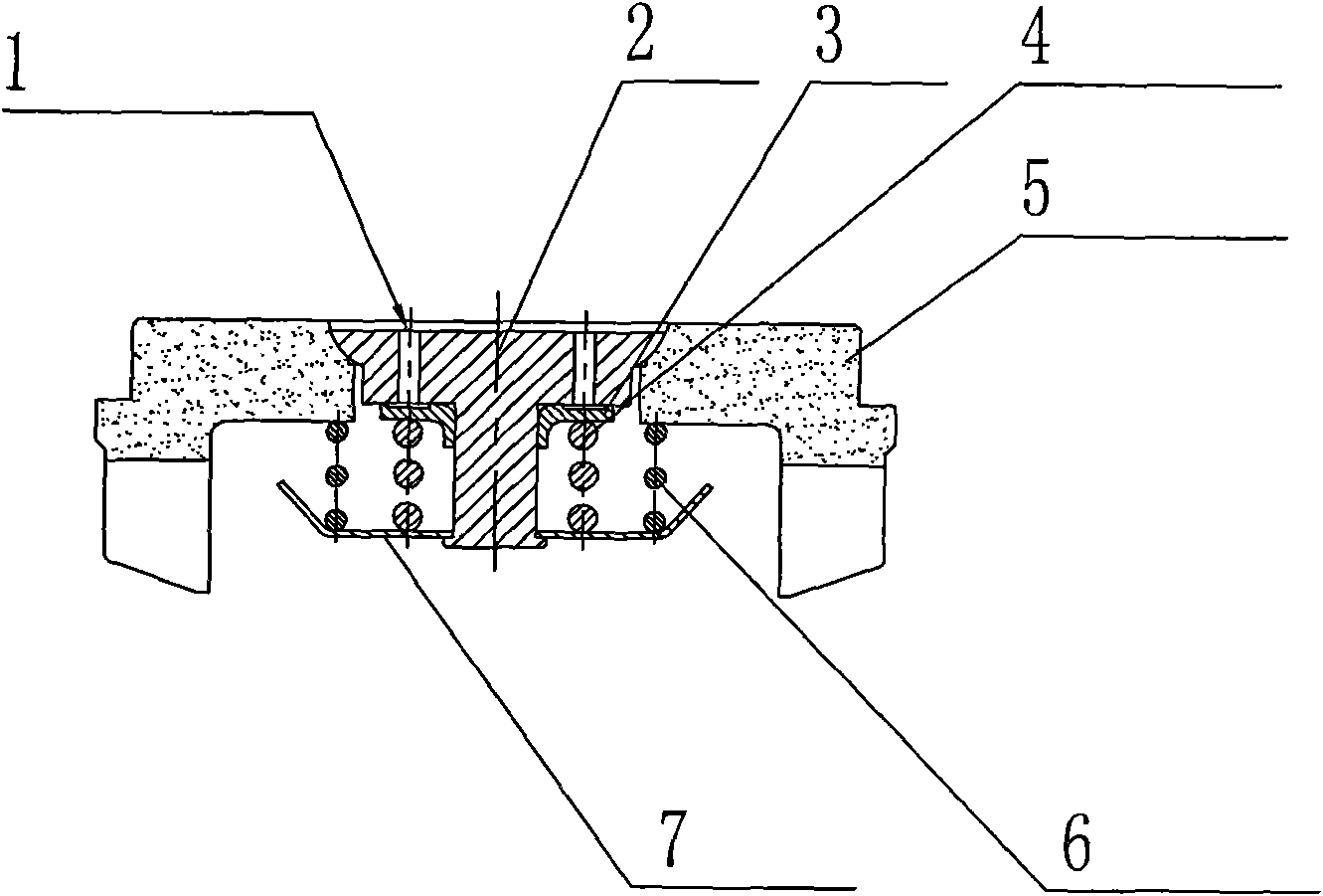
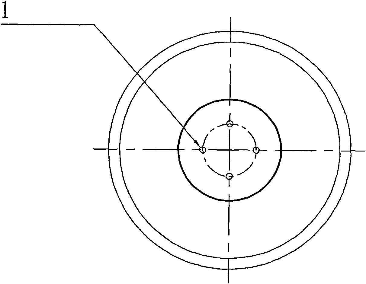
[0016] see Figure 1 to Figure 3 As shown, the new compression damping control valve introduced here is mainly used for shock absorbers, however, it should be understood that the present invention can also be used for other structural equipment requiring shock absorption.

[0017] This novel compression damping control valve includes a valve body 3, a compression valve seat 5, and a valve core 2. The valve core 2 is arranged on the compression valve seat 5, and the valve core 2 is in an inverted ...


PUM


Abstract

The invention discloses a novel compression damping control valve, which comprises a valve body, a compression valve seat and a valve element, wherein the valve element is arranged on the compression valve seat and is provided with at least one valve element throttle hole; the lower end face of the valve element is in pressed joint with the valve body; and the valve body is supported by and connected with a compression spring. The control valve of the invention has the advantages that: oil passes through the valve element throttle hole to undergo primary throttling and pressure reducing first and then continues to flow, and the valve body opens gradually after counteracting the force applied by the compression spring; because a limiting piece is configured in design, the valve body is limited when moving to a place where the valve body contacts the limiting piece and the novel compression damping control valve avoids generating plastic deformation under a limit throttling strength; and thus, under the condition of bearing a heavier compression hydraulic load, the resistance of the compression valve to deformation caused by accidental impact is ensured, and the service life and safety factor of the product are improved.

Description

technical field [0001] This invention relates to a control valve, and more particularly, to a novel compression damping control valve. Background technique [0002] For a long time, the compression valve assembly of the shock absorber has generally adopted a pure valve plate throttling structure, and the compression damping force of the shock absorber is realized by forming a throttling gap after the compression valve plate is deformed when it is subjected to oil pressure. In practice, we found that when the compression valve assembly with pure valve plate structure is subjected to occasional and unexpected large impacts, the plastic deformation or fracture of the compression valve plate often occurs, which leads to permanent failure of the compression valve assembly and loss of the shock absorber. Shock absorbing effect. With the development of society, more and more various heavy-duty vehicles are continuously introduced, and shock absorbers with greater damping force als...

Claims


Application Information

Patent Timeline
IPC IPC(8): F16F9/34
Inventor 朱荣
Owner ZHEJIANG WANXIANG SYST
Learn More