Damping pantograph for rail transit trains

A technology for pantographs and trains, which is applied in the field of rail transit, and can solve the problems of high manpower consumption, reduced service life of carbon skateboards, pantograph-catenary accidents, etc., and achieves the goal of improving service life and safety factor, increasing fatigue life, and reducing abnormal wear Effect

Pending Publication Date: 2019-10-15
SHANGHAI UNIV OF ENG SCI
View PDF0 Cites 2 Cited by
  • Summary
  • Abstract
  • Description
  • Claims
  • Application Information

AI Technical Summary

Problems solved by technology

[0005] Therefore, the abnormal wear of the carbon skateboard eventually leads to unstable pantograph followability, poor current quality, and even pantograph-catenary accidents; at the same time, the reduction of the service life of the carbon skateboard also requires a lot of manpower and financial resources to frequently replace it.
The abnormal wear of carbon skateboards not only increases the economic cost of train operation, but more importantly, it also brings great safety hazards

Method used


Image

  • Damping pantograph for rail transit trains
  • Damping pantograph for rail transit trains
  • Damping pantograph for rail transit trains

Examples


Embodiment 1

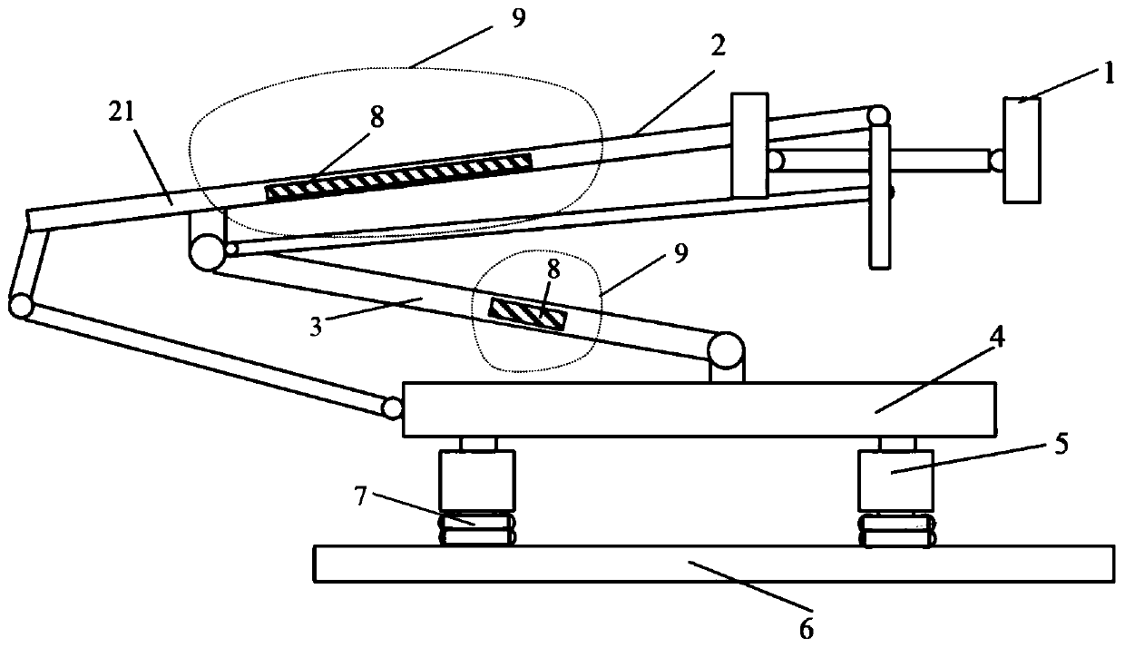
[0037] Such as figure 1 As shown, this embodiment provides a damping pantograph for rail transit trains. Although the structure of the pantograph varies according to different pantograph structural designs and the driving environment conditions of the locomotive, the basic structure Both include carbon skid plate 1 , upper frame 2 , lower arm 3 , pantograph base frame 4 , insulation 5 and roof mounting base 6 . In this embodiment, a resonant vibration force damping unit 8 and a vibration isolation unit 7 are also provided on the pantograph. The upper frame 2 is composed of the upper beam 21 and the cross beam. The upper beam 21, the cross beam and the lower arm 3 are all beam structures of the pantograph, which is also one of the parts that generate the most serious resonance response. The upper beam 21 and the crossbeam are mostly hollow tubes, and the lower arm 3 has both hollow tubes and other profiles. The upper beam 21, crossbeam and lower arm 3 in this embodiment all ad...

Embodiment 2

[0044] Such as Figure 5 with Image 6 As shown, the basic structure and principle of this embodiment are the same as the first example, the difference is that the harmonic dynamic damping unit 8 is arranged outside the beam structure instead of inside. The innermost layer of the harmonic vibration damping unit 8 is the elastic element layer 81 and is in close contact with the outer wall of the upper beam 21 , the cross beam or the lower arm 3 . Figure 5 Take the upper beam as an example. The elastic element layer 81 , the mass element layer 82 and the corresponding beam section together constitute the resonant damping beam 10 . The elastic element layer 81 and the mass element layer 82 are combined into one body by adhesive, vulcanization process or mechanical bonding. This design is applicable to any form of beams, including hollow tube beams and various profile beams with different cross-sections, such as Figure 7 The "T" shaped member shown, such as Figure 8 As sho...

Embodiment 3

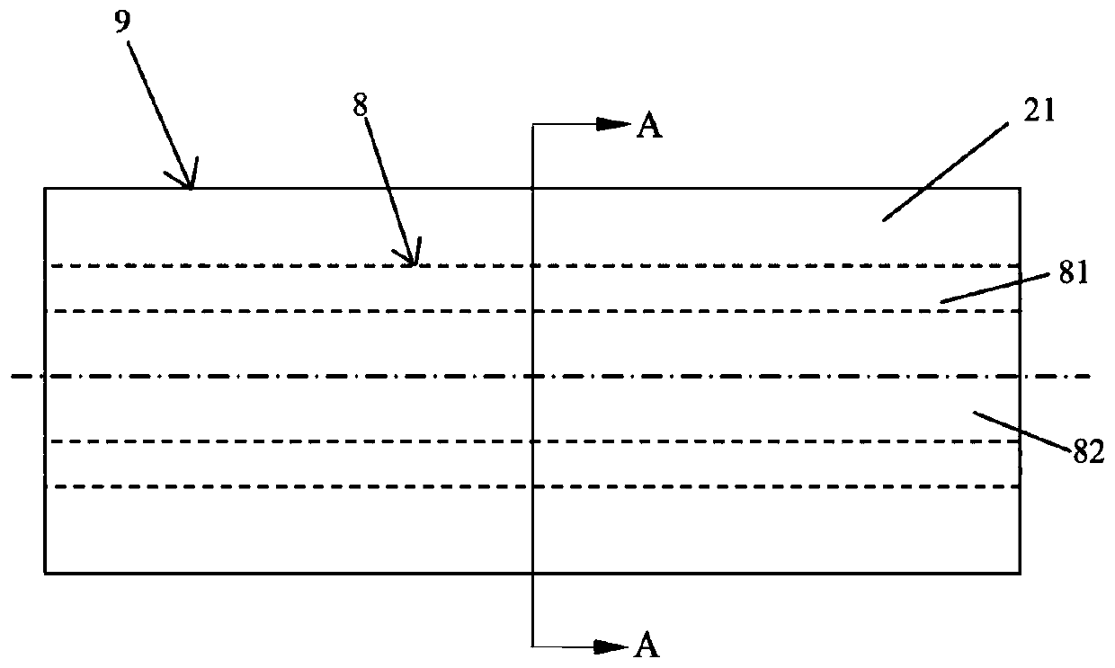
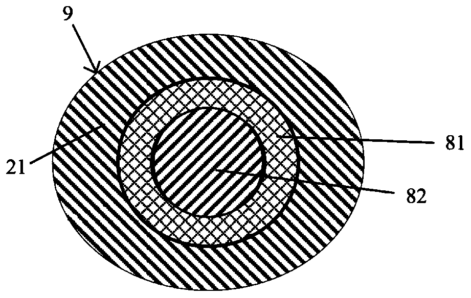
[0047] Such as Figure 9 with Figure 10 As shown, the basic structure and principle of this embodiment are the same as those of the first example, the difference is that the harmonic dynamic damping unit 8 is composed of a multi-layer elastic element layer 81 and a multi-layer mass element layer 82, which is used to deal with multiple high vibration Amplitude situation. Figure 9 Take the harmonic dynamic damping unit 8 composed of two layers of elastic element layers 81 and two layers of mass element layers 82 in the upper beam 21 as an example. The elastic element layer 81 and the mass element layer 82 are arranged at intervals, the outermost layer is the elastic element layer 81 close to the inner wall of the cavity, and the innermost layer is the mass element layer 82 .

[0048] A plurality of elastic element layers 81 and a plurality of mass element layers 82 form one or more dynamic vibration absorbers with different resonant frequencies, and the resonant frequency ra...


PUM

PropertyMeasurementUnit
Young's modulusaaaaaaaaaa

Abstract

The invention relates to a damping pantograph for rail transit trains. The damping pantograph comprises a carbon sliding plate, an upper frame, a lower arm rod, a pantograph base frame, an insulatingpart and a roof mounting base which are sequentially connected. The damping pantograph for rail transit trains is characterized in that: the damping pantograph further comprises a resonance power damping unit and a vibration isolation unit, the upper frame comprises an upper beam and a cross beam, the resonance power damping unit is installed on the upper beam, the cross beam or the lower arm rod,the vibration isolation unit is arranged between the insulating part and the roof mounting base. Compared with the prior art, the carbon sliding plate and a contact net point do not jump greatly, sothat abnormal abrasion of the pantograph is avoided, and the carbon sliding plate and the contact net point have economic and safe significance on daily operation of rail transit.

Description

technical field [0001] The invention relates to the field of rail transit and electrified railway technology, in particular to a damping pantograph with a vibration isolation and vibration absorption device. Background technique [0002] The pantograph is the current receiving device of the electrified railway train in rail transit. It is installed on the roof of the electric locomotive and is the electrical equipment for the electric locomotive to obtain electric energy from the catenary. In order to maintain the stability and continuity of the current receiving, the pantograph and catenary (conductor) need to maintain good followability. [0003] During the running of the train, due to the dynamic coupling characteristics between the ballast bed, the track and the wheels, vibration excitations of different amplitudes and frequencies will be caused, which will be directly transmitted to the pantograph base through the car body to cause the vibration of the pantograph . Th...

Claims


Application Information

Patent Timeline
IPC IPC(8): B60L5/20
CPCB60L5/205
Inventor 马子彦王安斌吴安伟
Owner SHANGHAI UNIV OF ENG SCI
Why Eureka
Try Eureka