All-steel truck radical tire structure

A radial tire, a technology in the width direction of the tire, applied to tire parts, reinforcement layers of pneumatic tires, vehicle components, etc., can solve the problem of tire shoulder delamination service life, insufficient step pressure, large interlayer shear force, etc. problems, achieve good rigidity distribution, reduce cracks, and reduce overall deformation

Active Publication Date: 2020-04-10
GITI RADIAL TIRE (ANHUI) CO LTD
View PDF23 Cites 2 Cited by
  • Summary
  • Abstract
  • Description
  • Claims
  • Application Information

AI Technical Summary

Problems solved by technology

[0002] At present, all-steel radial truck tires usually adopt a three-layer belt layer and two-layer 0-degree belt layer structure. The damage form of the crown position of this structure product in the market is basically the first belt layer and the end of the second belt layer. Damage leading to failure issues such as shoulder delamination of the tire and premature end of service life
The current way of laying the width of the belt layer is usually that the second belt layer is wider than the first belt layer, and it is laid on the top of the first belt layer, which leads to insufficient step pressing between the two during molding and pressing, forming The end of the belt layer cannot be fully bonded with the rubber compound, and the existing tire is prone to deformation of the shoulder. At the same time, the second belt layer is directly laid on the top of the first belt layer, and the first belt layer and the second belt layer The interlayer shear force between the two belt layers is large, which further aggravates the early failure of the cracks at the end of the belt layer and then develops into shoulder delamination. This defect causes premature failure of the tire. damage resulting in a shortened service life

Method used


Image

  • All-steel truck radical tire structure

Examples


Embodiment Construction

[0013] A preferred embodiment of the present invention will be described in detail below with reference to the accompanying drawings.

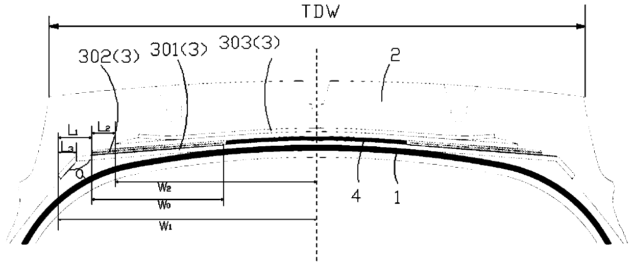
[0014] figure 1 A cross-sectional view in the meridian direction of the structure of the all-steel radial truck tire of the present invention is shown.

[0015] An all-steel radial truck tire structure, comprising a carcass 1, a tread 2 wrapped on the radially outermost periphery of the carcass, and a belt layer 3 arranged between the carcass and the tread, the belt layer comprising The first belt layer 301, the 0-degree winding belt layer 302 and the second belt layer 303 distributed in sequence from the carcass to the tread, wherein the 0-degree winding belt layer is wound in parallel with 5 steel wires as one strand to form a circumferential To the reinforcement layer, and its surface is coated with cover glue. The first belt layer, the second belt layer and the 0-degree winding belt layer are arranged in a trapezoidal shape, wherein the ...


PUM


Abstract

The invention provides an all-steel truck radical tire structure. The all-steel radial tire structure comprises a tire body, a tire tread coating the radial outermost periphery of the tire body, and abelt ply arranged between the tire body and the tire tread, the belt ply comprises a first belt ply, a 0-degree winding belt ply and a second belt ply which are sequentially distributed from the tirebody to the tire tread, and the first belt ply, the second belt ply and the 0-degree winding belt ply are arranged in a trapezoid shape, wherein the length 2W1 of the first belt ply in the tire widthdirection and the length 2W2 of the second belt ply in the tire width direction meets a relationship that W1>W2, and the length 2W1 of the first belt ply in the tire width direction and the horizontal width TDW of a crown meets a relationship that 0.81 <= 2W1/TDW <= 0.96. The paving mode of the 0-degree winding belt ply, the first belt ply and the second belt ply is optimally designed, so the problem that the end parts of the belt plies cannot be fully bonded with rubber materials is solved, thereby cracks at the end parts of the belt plies are reduced, the high-speed performance of the tireis improved, and the mileage service life of the tire is prolonged.

Description

technical field [0001] The invention relates to the technical field of tires, in particular to an all-steel load radial tire structure. Background technique [0002] At present, all-steel radial truck tires usually adopt a three-layer belt layer and two-layer 0-degree belt layer structure. The damage form of the crown position of this structure product in the market is basically the first belt layer and the end of the second belt layer. Damage leading to failures such as shoulder delamination and premature end of tire life. The current way of laying the width of the belt layer is usually that the second belt layer is wider than the first belt layer, and it is laid on the top of the first belt layer, which leads to insufficient step pressing between the two during molding and pressing, forming The end of the belt layer cannot be fully bonded with the rubber compound, and the existing tire is prone to deformation of the shoulder. At the same time, the second belt layer is dir...

Claims


Application Information

Patent Timeline
Patent Type & Authority Applications(China)
IPC IPC(8): B60C9/18
CPCB60C9/18
Inventor 费贤贵邓正武刘飞
Owner GITI RADIAL TIRE (ANHUI) CO LTD
Why Eureka
Try Eureka