Linear drive system

a linear drive and drive system technology, applied in the direction of propulsion systems, electrical apparatus, dynamo-electric machines, etc., can solve the problems of b>4/b>, performance degradation, and the rise of the movable table b>4, so as to improve the high-speed performance, high stability in the neutral position, and the effect of responding performan

Active Publication Date: 2009-03-03
NIPPON THOMPSON
View PDF4 Cites 5 Cited by
  • Summary
  • Abstract
  • Description
  • Claims
  • Application Information

AI Technical Summary

Benefits of technology

[0012]It is an object of the present invention to provide a linear drive system capable of dramatically improving high speed performance and response performance with simple structure.
[0019]According to the present invention, when both the mobile units relatively move from the neutral position, the magnetic forces of the permanent magnets act on the magnetic member. The acting force results in a force in a direction opposite to the moving direction of the first mobile unit when the first mobile unit moves from the neutral position to a stroke end. When the first mobile unit moves from the stroke end toward the neutral position, the acting force results in a force in a forward direction with respect to the moving direction of the first mobile unit. Thus, the force in the opposite direction acts as a damping force on the first mobile unit and the force in the forward direction results in a force thrusting the first mobile unit in the moving direction. In consequence, without an increase in size of a permanent magnet and / or an armature coil, the improvements of high-speed performance and response performance can be achieved.
[0020]Further, according to the present invention, because, when both the mobile units are in the neutral position, the two magnetic loops passing through the magnetic member are bilaterally symmetric with respect to the magnetic member, a high stability in the neutral position is achieved.
[0021]Still further, according to the present invention, a long stroke of movement of the mobile unit is provided.
[0022]Yet further, according to the present invention, the magnetic member is easily mounted on the mobile unit, and also on an existing mobile unit.

Problems solved by technology

However, a reduction in the thickness of the movable table 4 involves inferiority in rigidity, leading to a warp in the movable table 4.
Such a warp in the movable table 4 gives rise to degradation in performance.
This makes it close to impossible under the present circumstances to use any magnet with a stronger magnetic force.
However, an increase in size of such a component involves an increase in mass of the component.
Accordingly, even if the thrust can be increased, the increased thrust is wasted for the increased mass.
In consequence, the increase in electric current applied is limited.
In either case, the conventional drive systems have limits for the achievement of speedups or fast response.

Method used


Image

  • Linear drive system
  • Linear drive system
  • Linear drive system

Examples


first embodiment

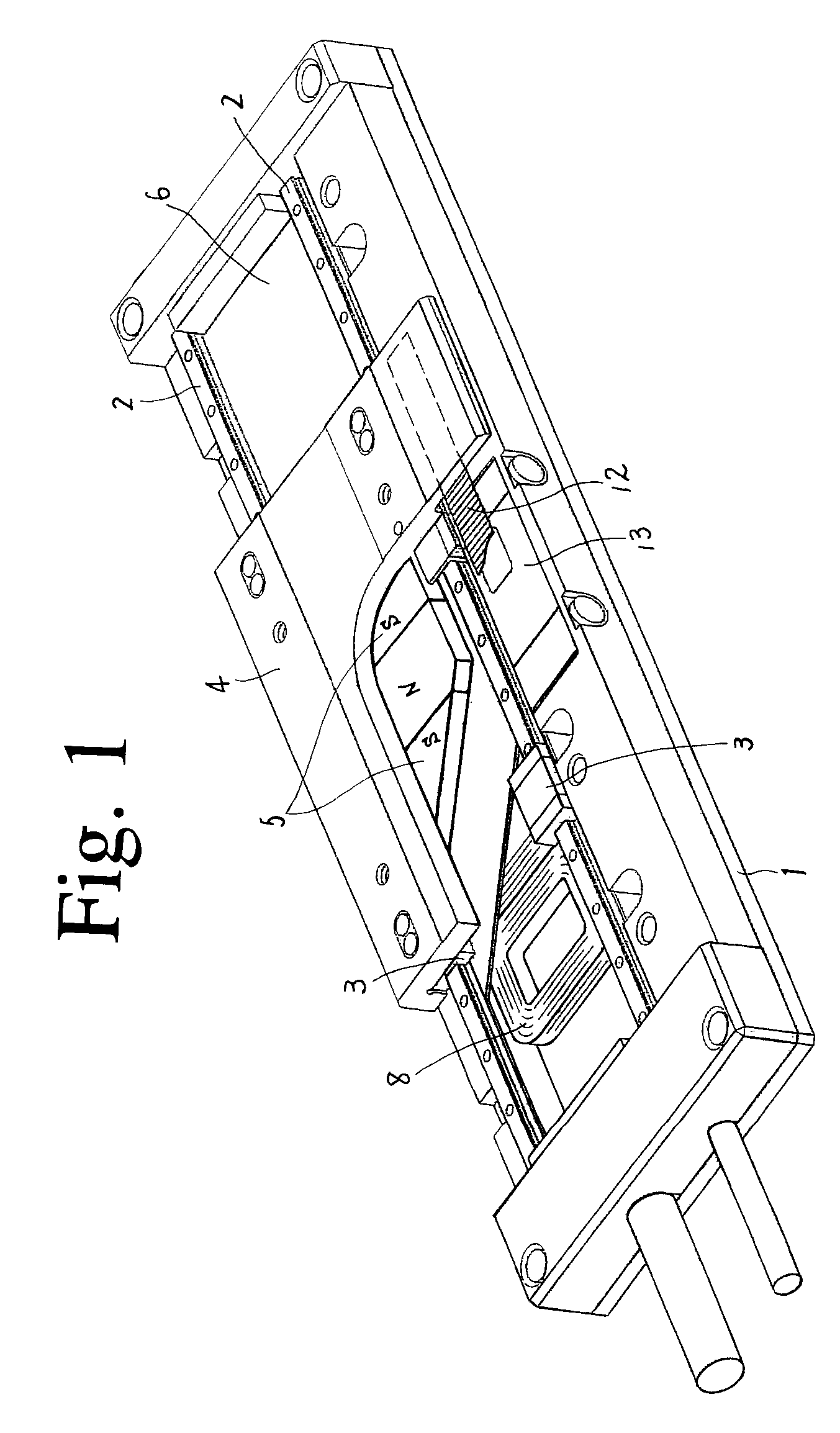
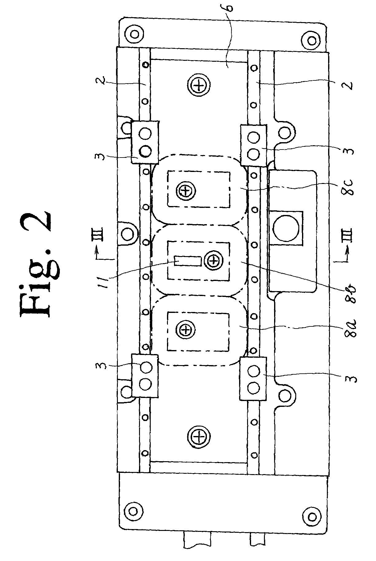
[0038]In the first embodiment illustrated in FIGS. 1 to 7, a pair of track rails 2 extending parallel to each other is laid on the bed 1 made of a ferromagnetic material. A plurality of sliders 3 are movably provided on the track rails 2. A movable table 4 made of a ferromagnetic material is fixed to the sliders 3 so that the movable table 4, together with the sliders 3, can reciprocate on the track rails 2.

[0039]The bed 1 form a second mobile unit of the present invention and the movable table 4 form a first mobile unit of the present invention.

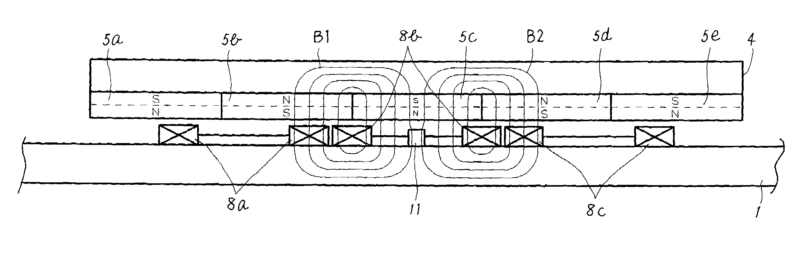
[0040]On the face of the movable table 4 facing the bed. 1, five permanent magnets 5 are arranged in a row in a direction of movement of the movable table 4. Each of the permanent magnets 5 is formed in a rectangular plate shape. Each of the permanent magnets 5 has a north pole and a south pole at its respective sides in the up-down direction in which the movable table 4 is located on the permanent magnet 5. The adjacent permanent magnets 5 ...

second embodiment

[0063]In the second embodiment, when the movable table 4 is in the neutral position shown in FIG. 8, the flux loops B1 and B2 pass through the respective magnetic members 14 and 15 in the vertical direction with respect to the magnetic member, so that the magnetic force is not strongest but has a maximum point. In consequence, the movable table 4 remains somewhat stable.

[0064]Then, the movable table 4 moves from the neutral position shown in FIG. 8 to the position shown in FIG. 9. In this moving process, the stable state of the magnetic fluxes with respect to the magnetic members 14 and 15, which is kept in the neutral position, is disrupted. In addition, as shown in FIG. 9, only the magnetic fluxes of the flux loops B1 and B3 pass through the respective magnetic members 14 and 15. At this point, a portion b of the magnetic flux enters each of the magnetic members 14 and 15 from an oblique direction with respect to the magnetic member. The portion b of the magnetic flux acts as a re...


PUM


Abstract

An improvement in high-speed and response performances is achieved with simple structure. A bed faces a movable table on which permanent magnets divided from each other in a stroke direction of the movable table are provided. One or more armature coils are provided on the bed facing the permanent magnets. Upon passage of an electric-current through the armature coils, an electromagnetic interaction between the armature coil current and magnetic fluxes of the permanent magnets produces a thrust force for relative movement between the two mobile units. A magnetic member is provided on the movable table in a position corresponding to a maximum point or a vicinity thereof of a magnetic force of the permanent magnets when the movable table is in a neutral position in the stroke direction. When the mobile units relatively move from the neutral position, the magnetic force of the permanent magnets acts on the magnetic member.

Description

BACKGROUND OF THE INVENTION[0001]1. Field of the Invention[0002]This invention relates to a linear drive system including linear motor essentially consisting of a permanent magnet and an armature coil.[0003]2. Description of the Related Art[0004]As one of the conventional drive system of the type described above, the invention disclosed in JP-A-2001-352744 is known. The conventional drive system is illustrated in FIGS. 13, 14. As is clear from these diagrams, a conventional linear drive system has a pair of parallel track rails 2 laid on a bed 1 made of a ferromagnetic material. A plurality of sliders 3 are movably provided on the track rails 2. A movable table 4 made of a ferromagnetic material is fixed to the sliders 3 so that the movable table 4 can reciprocate on the track rails 2.[0005]A plurality of permanent magnets 5 are arranged on the face of the movable table 4 facing the bed 1 in a direction of movement of the movable table 4. Each of the permanent magnets 5 is formed in...

Claims


Application Information

Patent Timeline
Patent Type & Authority Patents(United States)
IPC IPC(8): H02K41/00
CPCH02K41/03
Inventor OHNO, MASAKI
Owner NIPPON THOMPSON
Why Eureka
Try Eureka