High-frequency circuit, low noise block down converter and antenna apparatus
A high-frequency circuit, low-noise block technology, applied in the direction of circuits, antennas, electrical components, etc., can solve the problems of few types of materials, high dielectric constant, high price, etc., and achieve the effect of low cost
- Summary
- Abstract
- Description
- Claims
- Application Information
AI Technical Summary
Problems solved by technology
Method used
Image

Examples
Embodiment approach 1
[0070] (two-way satellite transceiver system)
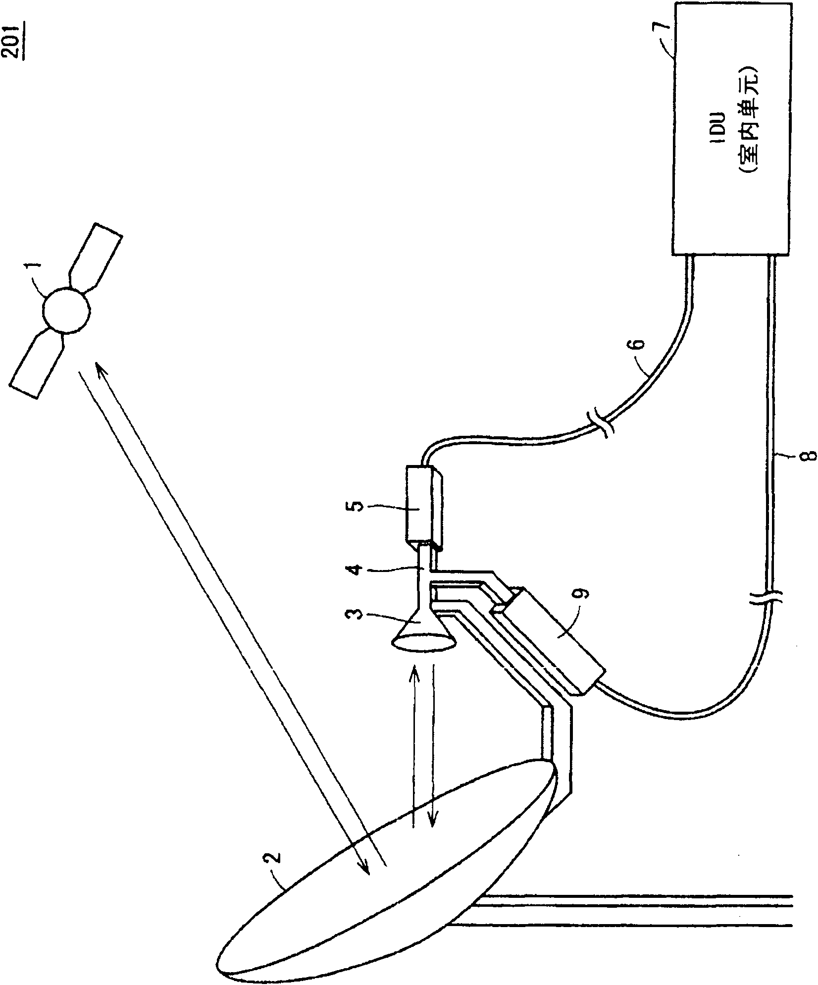
[0071] figure 1 It is a configuration diagram of a two-way satellite transmission and reception system including an LNB including the high-frequency circuit according to Embodiment 1 of the present invention.
[0072] refer to figure 1 , the two-way satellite transceiver system (antenna device) 201 includes: parabolic antenna 2, horn antenna 3, OMT (Orthogonal Mode Transfer: Orthogonal Mode Converter) 4, LNB (LowNoise Block down converter: low noise block down converter) 5, Coaxial cable 6 for reception, indoor unit 7 , coaxial cable 8 for transmission, and transmitter 9 .
[0073]An RF signal (wireless signal) transmitted from a two-way artificial satellite 1 is collected by a parabolic antenna 2 . The parabolic antenna 2 is also referred to as an "outdoor unit" with respect to the indoor unit 7 . The RF signal gathered by the parabolic antenna 2 is further gathered by the horn antenna 3 and sent to the OMT4. The OMT4 dem...
Embodiment approach 2
[0112] This embodiment relates to a high-frequency circuit in which the realization method of metal members is changed from the high-frequency circuit according to the first embodiment. Except for the content described below, it is the same as the high-frequency circuit according to Embodiment 1.
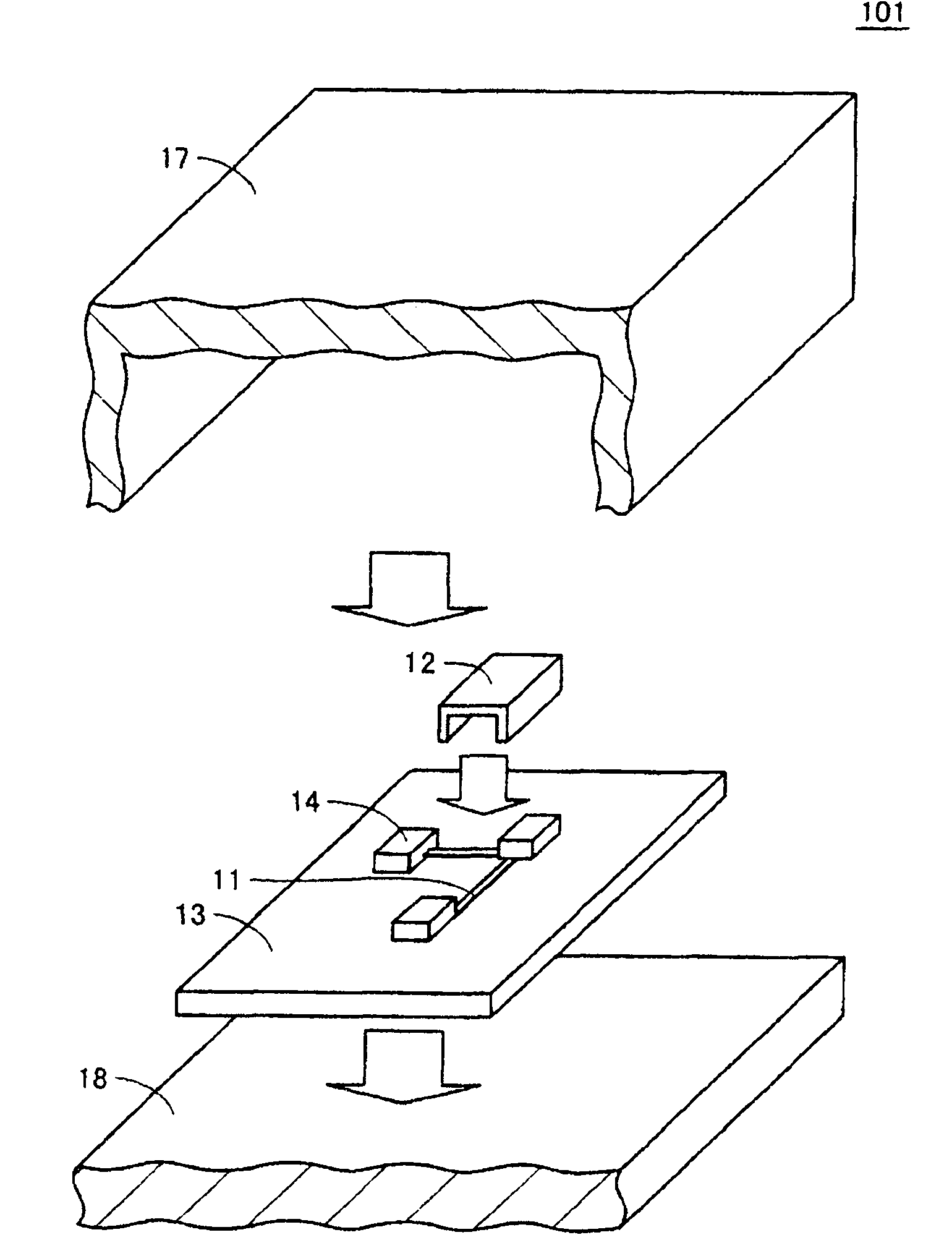
[0113] Figure 11 It is a perspective view showing the configuration of the high-frequency circuit according to Embodiment 2 of the present invention. Figure 12 It is a sectional view showing the structure of the high-frequency circuit according to Embodiment 2 of the present invention.
[0114] refer to Figure 11 and Figure 12 , the high-frequency circuit 102 includes: a signal pattern 11; a metal member 21; a dielectric substrate 13; an electronic component 14; a first ground pattern 16; a second ground pattern 15;
[0115] The metal shells 31, 32 are electrically connected to the second ground pattern 15 and the first ground pattern 16, accommodate and fix the signal patte...
Embodiment approach 3
[0121] This embodiment relates to a high-frequency circuit in which the realization method of metal members is changed from the high-frequency circuit according to the first embodiment. Except for the following description, it is the same as the high-frequency circuit according to the first embodiment.
[0122] Figure 13 It is a perspective view showing the configuration of the high-frequency circuit according to Embodiment 3 of the present invention. Figure 14 It is a sectional view showing the structure of the high-frequency circuit according to Embodiment 3 of the present invention.
[0123] refer to Figure 13 and Figure 14 , the high-frequency circuit 103 includes: a signal pattern 11; a dielectric substrate 13; an electronic component 14; a second ground pattern 15; a first ground pattern 16;
[0124] The dielectric substrate 13 includes a main surface S3 on which the electronic component 14 is mounted, and a main surface S4 provided on the opposite side of the ma...
PUM
 Abstract
Description
Claims
Application Information
 - R&D
- Intellectual Property
- Life Sciences
- Materials
- Tech Scout
- Unparalleled Data Quality
- Higher Quality Content
- 60% Fewer Hallucinations
Browse by: Latest US Patents, China's latest patents, Technical Efficacy Thesaurus, Application Domain, Technology Topic, Popular Technical Reports.
© 2025 PatSnap. All rights reserved.Legal|Privacy policy|Modern Slavery Act Transparency Statement|Sitemap|About US| Contact US: help@patsnap.com