Incident illumination device for a microscope

A technology of incident illumination and microscopy, applied in the direction of microscope, optics, instruments, etc., can solve the problems of difficult repeated operation and direct detection

Active Publication Date: 2010-12-01
LEICA MICROSYSTEMS (SCHWEIZ) AG
View PDF13 Cites 11 Cited by
  • Summary
  • Abstract
  • Description
  • Claims
  • Application Information

AI Technical Summary

Problems solved by technology

However, the method disclosed in this application has the disadvantage that each of the multiple LEDs must have a lens to somehow magnify and overlap the images of the source surfaces of the individual light sources to obtain uniform white light illumination
These adjustments are not easily perceptible directly and, therefore, difficult to repeat

Method used


Image

  • Incident illumination device for a microscope
  • Incident illumination device for a microscope
  • Incident illumination device for a microscope

Examples


Embodiment Construction

[0034] Described below figure 1 and figure 2 , where similar parts have the same reference numerals.

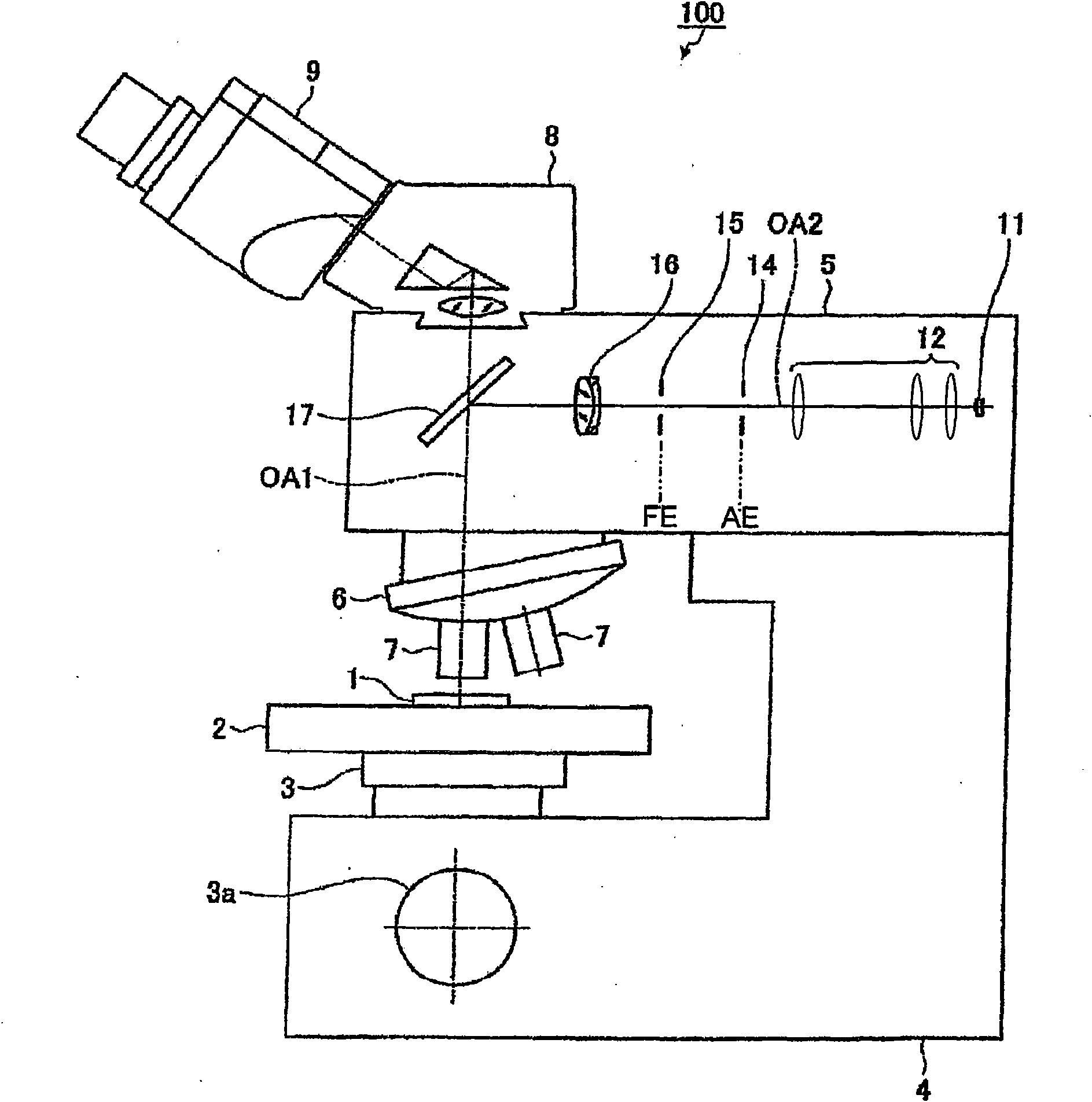
[0035] see figure 1 , schematically shows a cross-sectional view of a microscope, generally designated 100 , for studying the sample 1 . The microscope has a microscope body 4 on which a microscope stage 2 is mounted via a support member 3 . The sample 1 is placed on the microscope stage 2 and can be moved vertically by means of adjustment means in the form of a wheel 3a. Each objective lens 7 is provided on the objective turret 6 . Incident illumination 5 is provided to illuminate the sample 1 . Illumination light reflected from the sample 1 travels along the observation beam path through the tube 8 to the eyepiece 9 . The optical axis of the observation beam path is indicated with OA1.

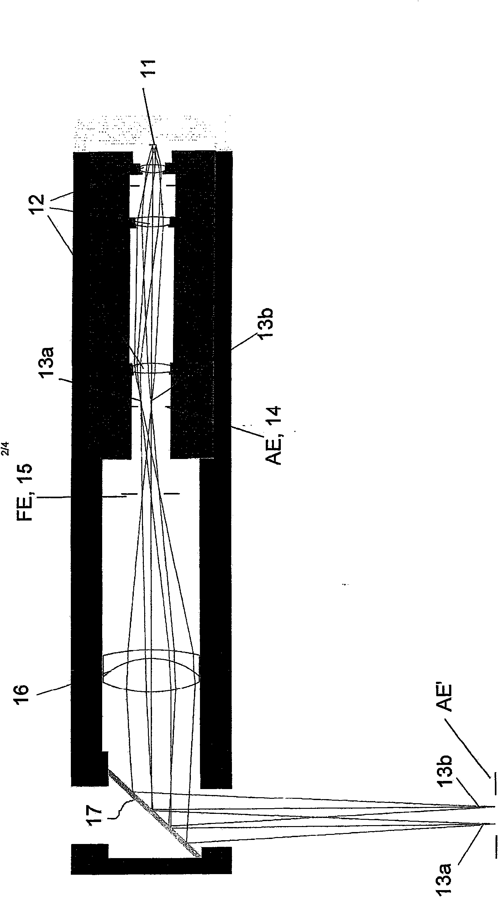
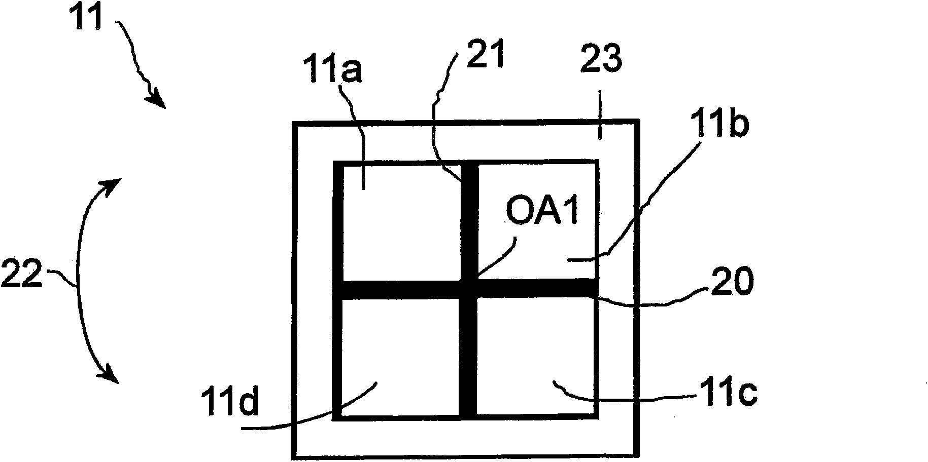
[0036] The incident illumination device 5 comprises a light source 11 which is imaged by a first lens system 12 onto an aperture plane AE. The aperture stop 14 is arranged on the a...


PUM


Abstract

The present invention relates to an incident illumination device(5) for a microscope (100), comprising a light source (11) that includes at least two light-emitting segments and is imaged into an aperture plane (AE) of the incident illumination device (5). At least one of the at least two light-emitting segments of the light source (11) is designed to be activated individually. The described microscope and methods of use thereof allow also to select between angular or oblique incident illumination.

Description

technical field [0001] The present invention relates to an incident illumination device for a microscope, a microscope using such an incident illumination device, and an incident illumination method that can be realized with such an incident illumination device. Background technique [0002] Due to the many benefits of LEDs (Light Emitting Diodes) over traditional incandescent or high pressure lamps, modern microscopes are increasingly using LEDs as light sources. LEDs generally last longer, are durable, are smaller, and generate much less heat. [0003] For example, WO 2006 / 136406 A1 describes a trans-illumination device with a plurality of LEDs. However, the method disclosed in this application has the disadvantage that each of the multiple LEDs must have a lens to somehow magnify and overlap the images of the source surfaces of the individual light sources to obtain uniform white light illumination. This involves quite a complex design. [0004] Japanese patent applica...

Claims


Application Information

Patent Timeline
Patent Type & Authority Applications(China)
IPC IPC(8): G02B21/06
CPCG02B21/12G02B21/06
Inventor R·保卢斯
Owner LEICA MICROSYSTEMS (SCHWEIZ) AG
Why Eureka
Try Eureka