Positioning mould holder of microscope
A technology for microscopes and mold bases, applied in microscopes, optics, instruments, etc., can solve problems such as low production efficiency, unstable product quality, and difficulty in the smoothness of wire drawing die holes, and achieve the effect of improving observation efficiency and quality
Inactive Publication Date: 2010-12-08
铜陵市精品工具模具有限责任公司
View PDF0 Cites 1 Cited by
- Summary
- Abstract
- Description
- Claims
- Application Information
AI Technical Summary
Problems solved by technology
[0003] The purpose of the present invention is to solve the problems that it is difficult to observe the smoothness of the wire drawing die hole with a microscope, which leads to low production efficiency and unstable product quality.
Method used
View moreImage
Smart ImageViewing Examples

Examples
Embodiment Construction
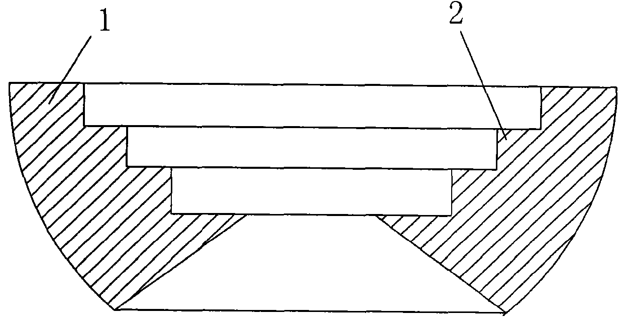
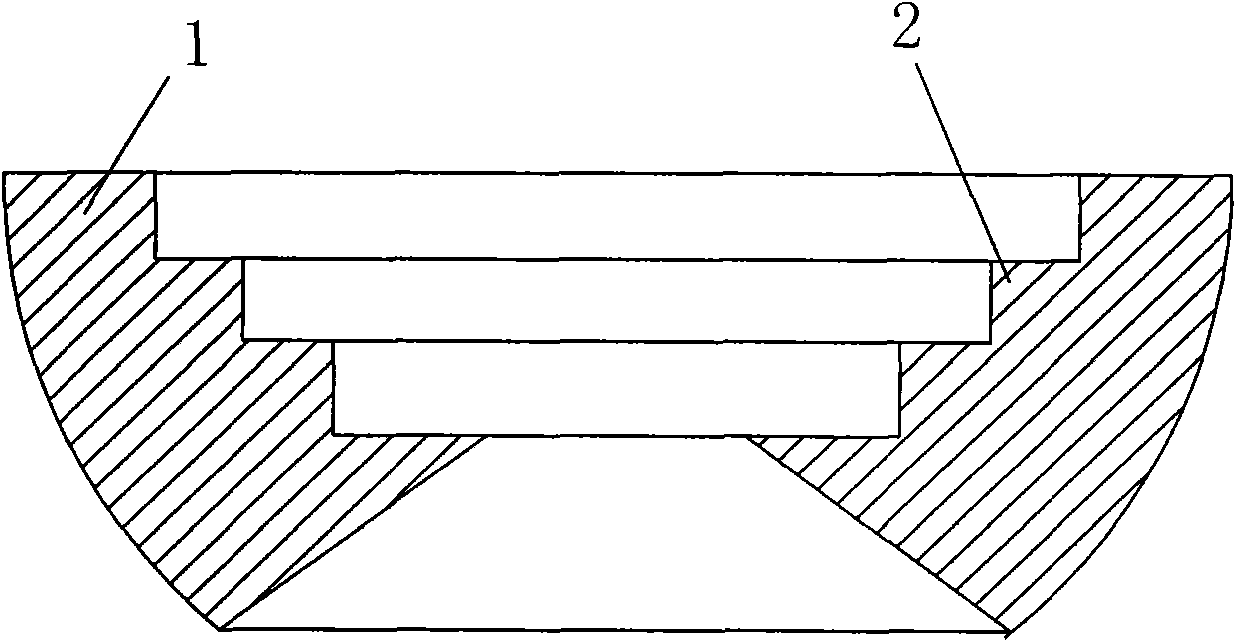
[0008] Such as figure 1 As shown, the microscope positioning mold base is composed of a spherical segment 1, and the center of the spherical segment 1 is provided with a cavity, and several coaxial annular stepped grooves 2 for placing different molds are provided in the cavity.
Login to View More PUM
 Abstract
The invention discloses a positioning mould holder of a microscope consisting of a segment (1). The centre of the segment (1) is provided with a hollow cavity, and the hollow cavity is provided with a plurality of coaxial annular stepped grooves (2) for containing different moulds. The invention can observe a wire-drawing mould from all angles, thereby the observation is not labor-consuming and time-consuming, the observation efficiency is greatly improved, and the quality of the product is improved.
Description
technical field [0001] The invention relates to a stage for placing workpieces of a microscope. Background technique [0002] In the production of wire drawing dies, the processed wire drawing dies need to be observed under a microscope for the smoothness of the wire drawing die hole. There is a through hole reserved on the workpiece placing table of the microscope, and the customer can set the workpiece table according to the needs. At present, when producing wire drawing dies to observe the smoothness of the holes through a microscope, the worker holds the wire drawing die in one hand and adjusts the focus with the other hand for observation. Because it is very difficult to change the angle of the drawing die with one hand, it is also very difficult to observe the smoothness of the drawing die, so the production efficiency is low and the product quality is unstable. Contents of the invention [0003] The purpose of the invention is to solve the problems that it is diff...
Claims
Login to View More Application Information
Patent Timeline
 IPC IPC(8): G02B21/24
Inventor 陈光宝程路平
Owner 铜陵市精品工具模具有限责任公司
Features
- R&D
- Intellectual Property
- Life Sciences
- Materials
- Tech Scout
- Unparalleled Data Quality
- Higher Quality Content
- 60% Fewer Hallucinations
Learn More Browse by: Latest US Patents, China's latest patents, Technical Efficacy Thesaurus, Application Domain, Technology Topic, Popular Technical Reports.
© 2025 PatSnap. All rights reserved.Legal|Privacy policy|Modern Slavery Act Transparency Statement|Sitemap|About US| Contact US: help@patsnap.com