Quick focusing microscope

A microscope and fast technology, applied in the field of biomedical imaging, can solve the problems of limited movement accuracy of the stage, inaccurate focus, complex structure, etc., to avoid changes in mechanical accuracy, reduce labor intensity, and improve observation efficiency.

Inactive Publication Date: 2017-05-24
梅木精密工业(珠海)有限公司
View PDF7 Cites 7 Cited by
  • Summary
  • Abstract
  • Description
  • Claims
  • Application Information

AI Technical Summary

Problems solved by technology

Due to the complex structure of the mechanical focusing method of the microscope, the movement accuracy of the stage is limited by the mechanism, which cannot meet the requirements of fast focusing, and may easily cause inaccurate focusing and out-of-focus phenomena. Real-time mechanical focusing is required to ensure the clear imaging of the specimen.
This observation method uses the lower surface of the slide as a reference. The thickness tolerance of the slide also has a certain influence on the focal point of the objective lens. The position of the observation surface of the same slide will also change. Repeated focusing is also required to clearly observe the image of the specimen.
Therefore, the operation of the traditional microscope is extremely cumbersome and complicated, and the operator needs to be familiar with its performance to observe the slide specimen correctly, and it is not conducive to the automatic device to observe the same or multiple slide specimens, and the repeated focusing work is cumbersome

Method used


Image

  • Quick focusing microscope
  • Quick focusing microscope
  • Quick focusing microscope

Examples


Embodiment Construction

[0024] In the following, the concept, specific structure and technical effects of the present invention will be clearly and completely described in conjunction with the embodiments and the drawings to fully understand the purpose, features and effects of the present invention. Obviously, the described embodiments are only a part of the embodiments of the present invention, rather than all of them. Based on the embodiments of the present invention, other embodiments obtained by those skilled in the art without creative work belong to The scope of protection of the present invention.

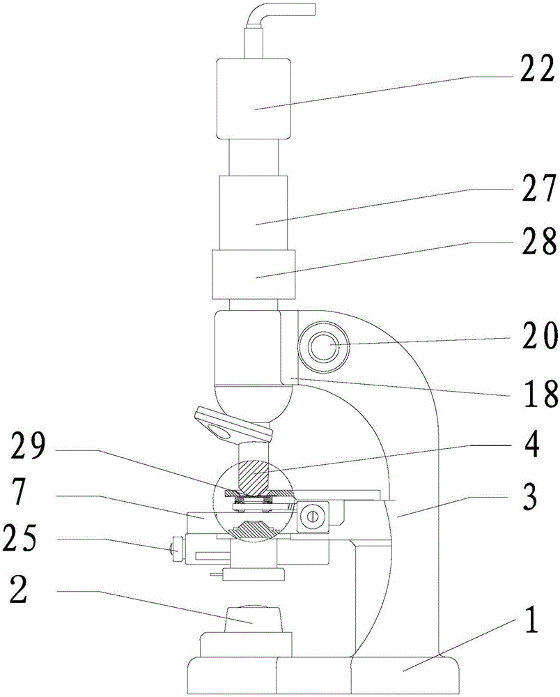
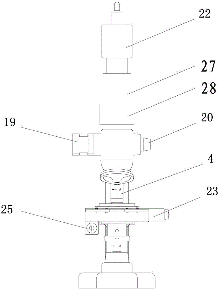
[0025] Reference Figure 1 to Figure 6 , A fast focusing microscope, comprising a base 1, a light source 2 arranged on the base 1, and a mirror arm 3 connected to the base 1. The upper end of the mirror arm 3 is provided with a focusing assembly, and the focusing assembly includes a The objective lens 4, the arm 3 is fixed with a horizontal positioning reference plate 5, the positioning reference pl...


PUM


Abstract

The invention relates to a quick focusing microscope. The invention aims at solving the problems that a mechanical focus adjusting method of a microscope is complicated in structure, the movement precision of an objective table is limited by a tolerance, a quick focus adjusting requirement cannot be met, further, an influence can be generated to a focal distance by the thickness tolerance of a slide and the focus adjustment needs to be carried out anew when the slide is replaced each time in the prior art. The invention discloses the quick focusing microscope, wherein a relatively fixed positioning datum plate is arranged below an objective lens as a focusing datum; further, a liquid lens is arranged in the light path of the microscope and can realize quick zooming. When a CCD (Charge Coupled Device) camera recognizes that an observed object generates defocusing, the focal power of the liquid lens can be changed through adjusting the size of the voltage or the current of a driver for the liquid lens. Thus, the purpose of extending a depth of field is achieved to realize a zooming function, so as to meet a real-time imaging requirement. The quick focusing is realized in the condition that the provision of other mechanical part is not needed.

Description

Technical field [0001] The invention relates to the field of biomedical imaging, in particular to a fast focusing microscope. Background technique [0002] The traditional microscope observation is to clamp the glass slide to be observed on the specimen holder of the stage with a press, and move the stage with the lower surface of the glass slide as a reference to observe the slide specimen. Due to the complicated structure of the mechanical focusing method of the microscope, the moving accuracy of the stage is limited by the mechanism, which cannot meet the requirements of fast focusing. It is easy to cause inaccurate focusing and defocusing. Real-time mechanical focusing is required to ensure the clear imaging of the specimen. In this observation method that uses the lower surface of the glass slide as a reference, the thickness tolerance of the glass slide also has a certain impact on the focus of the objective lens. The observation surface of the same glass slide will also ch...

Claims


Application Information

Patent Timeline
Patent Type & Authority Applications(China)
IPC IPC(8): G02B21/24G02B21/26G02B21/36
CPCG02B21/241G02B21/242G02B21/26G02B21/361
Inventor 杨宏伟
Owner 梅木精密工业(珠海)有限公司
Why Eureka
Try Eureka