Machining device and method for machining material

A processing equipment, processing head technology, applied in the direction of metal processing equipment, analysis materials, welding equipment, etc., to achieve cost-effective and compact effect

Active Publication Date: 2010-02-10
普莱斯泰克光电子有限公司
View PDF0 Cites 14 Cited by
  • Summary
  • Abstract
  • Description
  • Claims
  • Application Information

AI Technical Summary

Problems solved by technology

The process control of the processing beam is therefore only possible with a time delay

Method used


Image

  • Machining device and method for machining material
  • Machining device and method for machining material
  • Machining device and method for machining material

Examples


Embodiment Construction

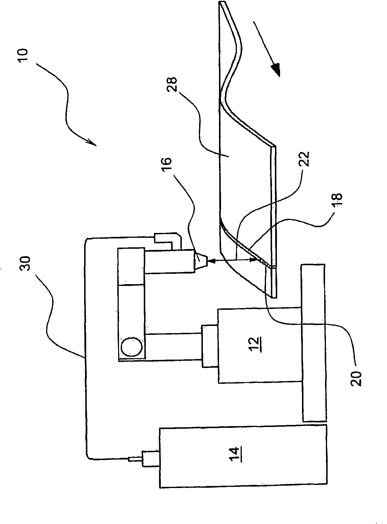
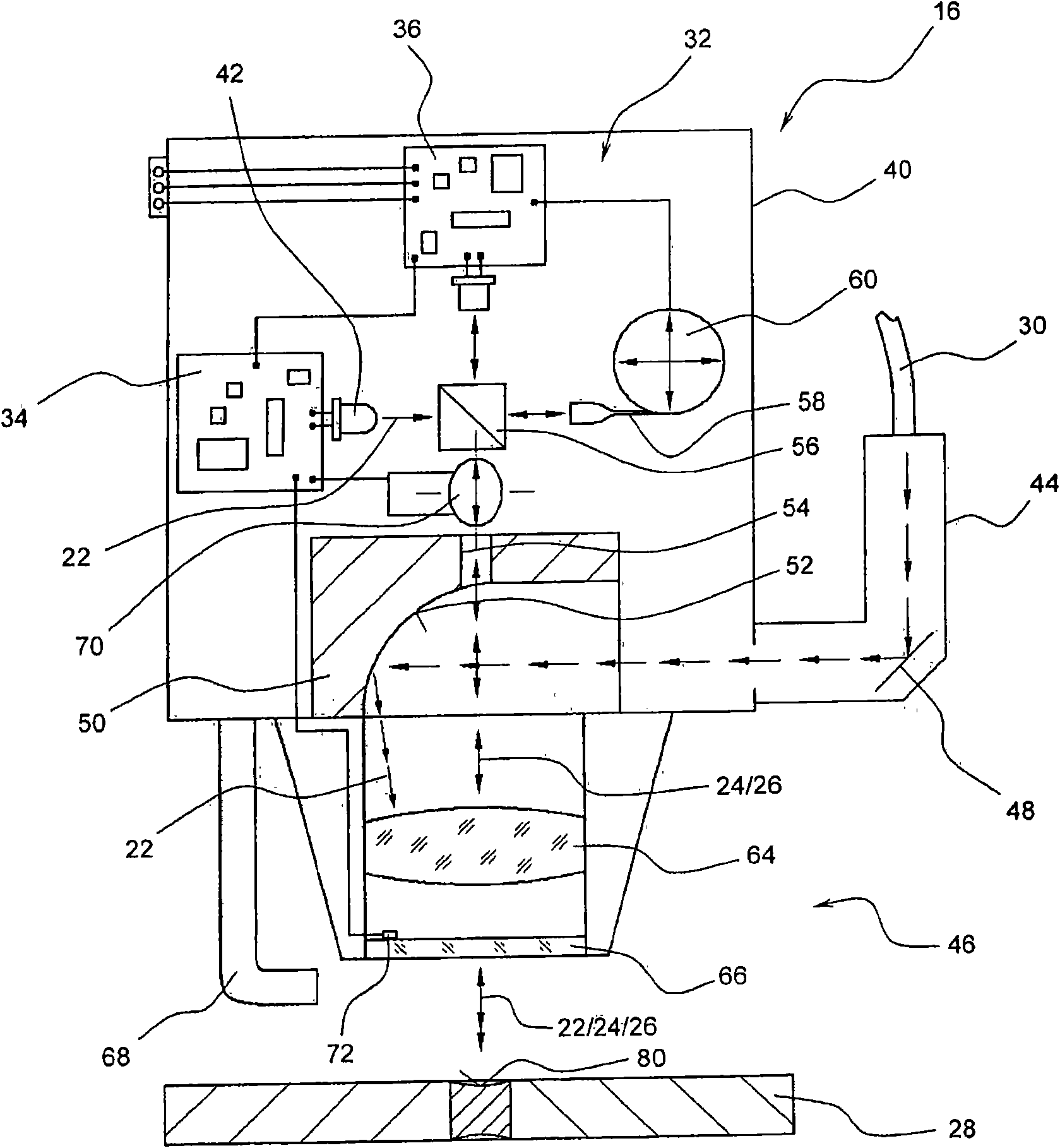
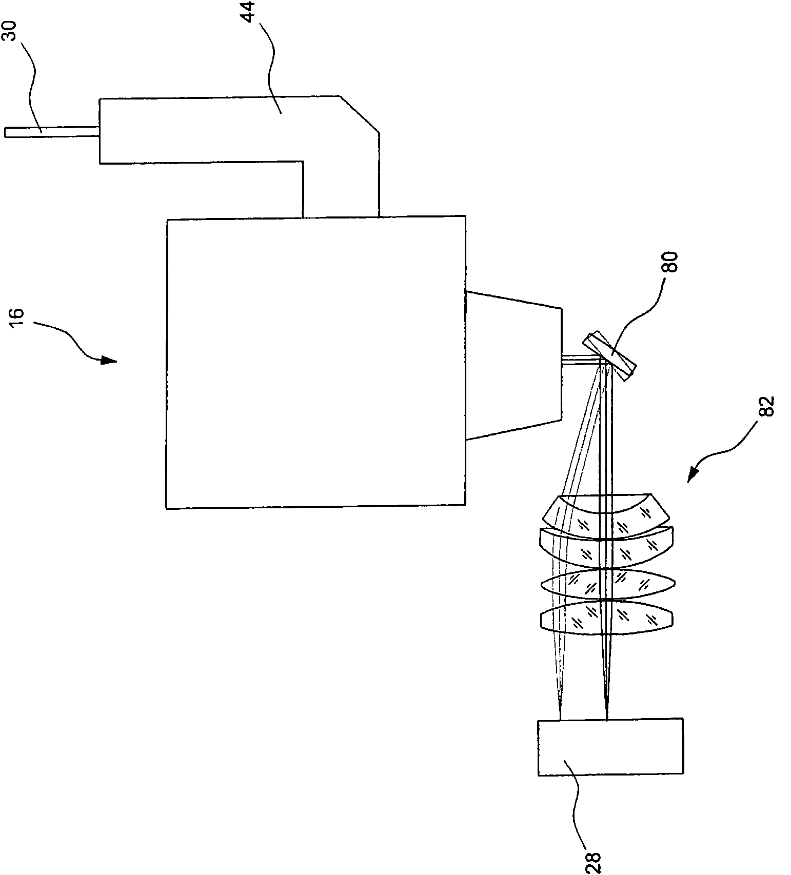
[0035] exist figure 1 A processing device 10 is shown in , which mainly consists of an industrial robot 12 , a laser source 14 and a processing head 16 carried by the industrial robot 12 . The industrial robot 12 is a multi-axis robot which can bring the machining head to different spatial positions relative to the workpiece 28 in order to ensure favorable machining of the workpiece 28 . The laser source 14 is connected to the processing head 16 by means of a bendable fiberglass line 30 . Here, the laser light generated by the laser source 14 is input to the processing head 16 provided in the figure 2 The optical system is shown in detail in . The laser output from the optical system is aimed at the workpiece 28 as a high-energy machining beam 22 .

[0036] In the processing head 16, in addition to the optical system for the high-energy processing beam 22, there are also figure 2 An optical coherence tomography device 32 , shown in detail in , is used to determine the su...


PUM

PropertyMeasurementUnit
wavelengthaaaaaaaaaa

Abstract

The invention relates to a machining device (10) comprising at least one machining head (16) designed to provide at least one high-energy machining beam (22), especially an electron or laser beam. Such a machining device is used to remove material from workpieces (28) or for connecting workpieces (28) by bonding, especially by means of welding. According to the invention, at least one scanning device (32) designed as an optical coherence tomograph and provided for surface scanning is associated with the machining head (16). The invention also relates to a method for machining material using ahigh-energy machining beam for scanning surface areas of a workpiece which is machined, not yet machined, or being machined, by means of an optical coherence tomograph.

Description

technical field [0001] The invention relates to a processing device having at least one processing head which is designed to deliver at least one high-energy processing beam, in particular an electron beam or a laser beam. Background technique [0002] Machining devices known on the market enable a relative movement between one or more workpieces to be machined and a machining head for eroding and / or joining material machining. The processing head is equipped with an integrated or separate source of high-energy processing beams, in particular laser beams or electron beams. Typical fields of application of such processing devices are the erosion of workpiece material by means of laser beams or the welding of plastic or metal parts by means of electron beams or laser beams. Depending on the field of application, strict quality requirements are imposed on such machining processes, wherein precise guidance of the high-energy machining beam relative to the workpiece and control ...

Claims


Application Information

Patent Timeline
Patent Type & Authority Applications(China)
IPC IPC(8): B23K26/03B23K26/04G01N21/17G01B9/02
CPCB23K26/04B23K26/046G01N21/4795B23K26/03B23K26/032
Inventor C·迪亚茨M·科戈尔-霍拉切尔
Owner 普莱斯泰克光电子有限公司
Why Eureka
Try Eureka