Multi-beam selection smart antenna array and system having antenna array

A smart antenna and multi-beam technology, applied in the field of wireless communication, can solve the problems of reduced receiving sensitivity, no way to communicate, and increased difficulty coefficient, so as to reduce the antenna coverage angle, reduce the intensity of competition, and reduce mutual interference. Effect

Active Publication Date: 2016-06-22
淮北市宇控信息技术有限公司
View PDF5 Cites 14 Cited by
  • Summary
  • Abstract
  • Description
  • Claims
  • Application Information

AI Technical Summary

Problems solved by technology

[0004] Many users have a deep understanding. In densely populated areas such as hospitals, coffee shops, exhibition halls or shopping malls, there is obviously a free WIFI signal and the signal strength is strong, so they can connect, but they just cannot access the Internet.
This is because the WIFI standard protocol is a conflict detection/conflict avoidance strategy. When the number of connected terminals reaches more than 32, users’ requests to access the Internet increase, and the competition for bandwidth is very serious, causing everyone to be unable to communicate.
Just like the expressway has 3 lanes, but there are 10 traffic flows on the expressway, the congestion causes the traffic flow to be slow, or even stagnant, so there is no way to circulate
[0005] 2. Interference problem
For example, if the conference room has a capacity of 100-200 people, and to satisfy 100-200 people surfing the Internet at the same time, it is necessary to in

Method used


Image

  • Multi-beam selection smart antenna array and system having antenna array
  • Multi-beam selection smart antenna array and system having antenna array
  • Multi-beam selection smart antenna array and system having antenna array

Examples


Embodiment Construction

[0040] In order to make the object, technical solution and advantages of the present invention clearer, the present invention will be further described in detail below in conjunction with the accompanying drawings and embodiments. It should be understood that the specific embodiments described here are only used to explain the present invention, not to limit the present invention.

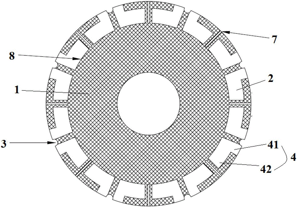
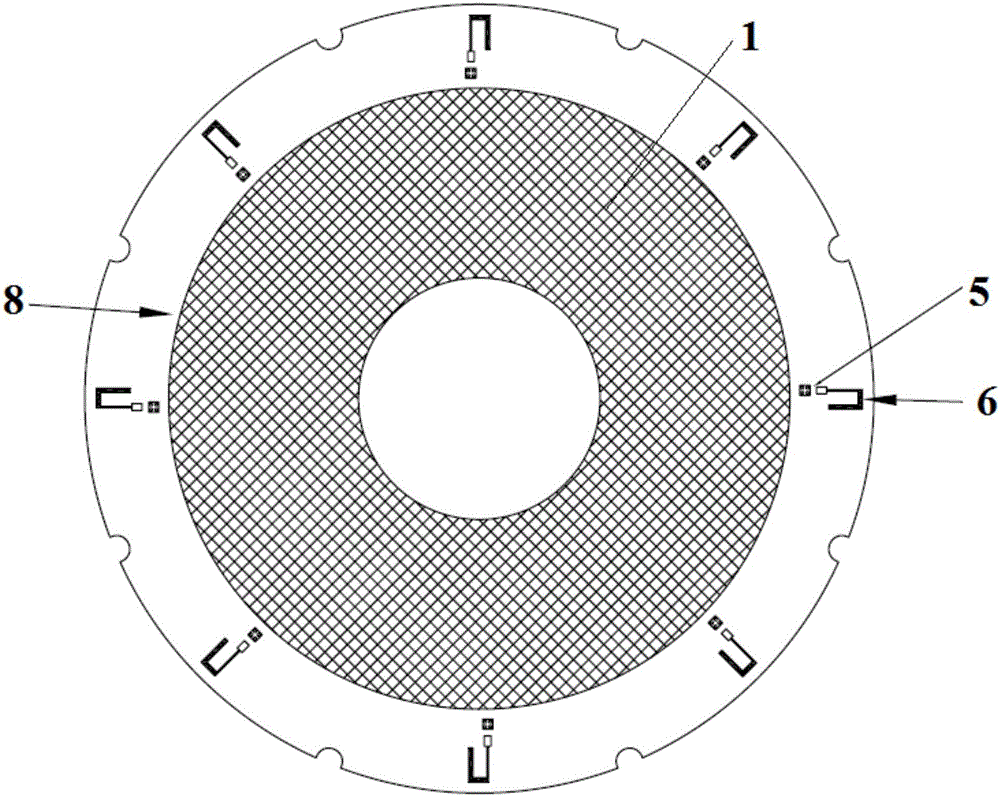
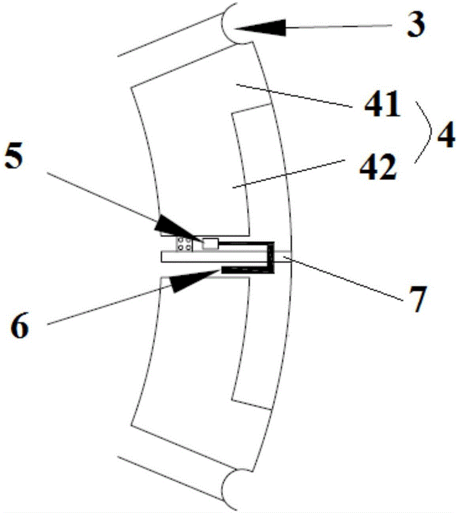
[0041] This embodiment will introduce a complete multi-beam selection smart antenna communication system, which mainly includes three parts: antenna array, antenna control system and software control module. The antenna array is set as a circular array: multi-beam selection smart antenna array, each antenna element is designed as a directional antenna, the beam of the antenna element points to the direction of the line connecting the center of the array and the center of the array element outward, according to the number of antenna elements Select different array element antenna beamwidths to ensur...


PUM


Abstract

The invention discloses a multi-beam selection smart antenna array and a system having the antenna array. The antenna array comprises a substrate, and a plurality of antenna array elements fixed on the substrate; the substrate is circular, and the centers of all antenna array elements around the substrate are uniformly distributed on a round outer periphery of one side of the substrate to form an annular array; the substrate is configured with a plurality of arc-shaped sags and a plurality of slits from the round end face of the substrate towards the center, and one arc-shaped sag is arranged between two adjacent antenna array elements, and an antenna isolation belt is formed thereby; each antenna array element comprises two antenna elements, and one slit is arranged between two antenna elements to form an antenna coupling slit thereby; and antenna feed points of the antenna array elements are located between two antenna elements. The structure provided by the invention can realize omnidirectional spatial scan. The invention further discloses a multi-beam selection smart antenna communication system adopting the antenna array.

Description

technical field [0001] The invention relates to a multi-beam selection smart antenna array in the technical field of wireless communication, in particular to a multi-beam selection smart antenna array and a multi-beam selection smart antenna communication system using the antenna array. Background technique [0002] With the continuous development and improvement of WIFI technology, WIFI has become an indispensable means of communication in people's daily life, and has also become an extremely convenient communication technology favored by governments and enterprises. Especially in the new round of smart city construction boom, WIFI technology will surely shine. However, many problems have occurred during the commercialization of WIFI, and many of these problems have seriously affected the user experience of end users. [0003] 1. System capacity problem [0004] Many users have a deep understanding that in densely populated areas such as hospitals, coffee shops, exhibitio...

Claims


Application Information

Patent Timeline
IPC IPC(8): H01Q21/00H01Q1/36H01Q1/52H01Q13/10H04B7/04
CPCH01Q1/36H01Q1/521H01Q13/106H01Q21/00H04B7/0408
Inventor 姚定军卢苇傅强
Owner 淮北市宇控信息技术有限公司
Why Eureka
Try Eureka