Self-oscillating regulated low-ripple charge pump and method

一种电荷泵、电路的技术,应用在电气元件、功率的自动控制、没有中间变换为交流的变换设备等方向,能够解决损失、浪费能量等问题

Active Publication Date: 2010-12-22
TEXAS INSTR INC
View PDF2 Cites 17 Cited by
  • Summary
  • Abstract
  • Description
  • Claims
  • Application Information

AI Technical Summary

Problems solved by technology

Whenever the flying capacitor function is effectively swapped, some energy is lost or wasted due to the need to recharge one of the parasitic capacitances Cp1 or Cp2
What is actually lost is the current required to recharge the parasitic capacitance Cp1 or Cp2

Method used


Image

  • Self-oscillating regulated low-ripple charge pump and method
  • Self-oscillating regulated low-ripple charge pump and method
  • Self-oscillating regulated low-ripple charge pump and method

Examples


Embodiment Construction

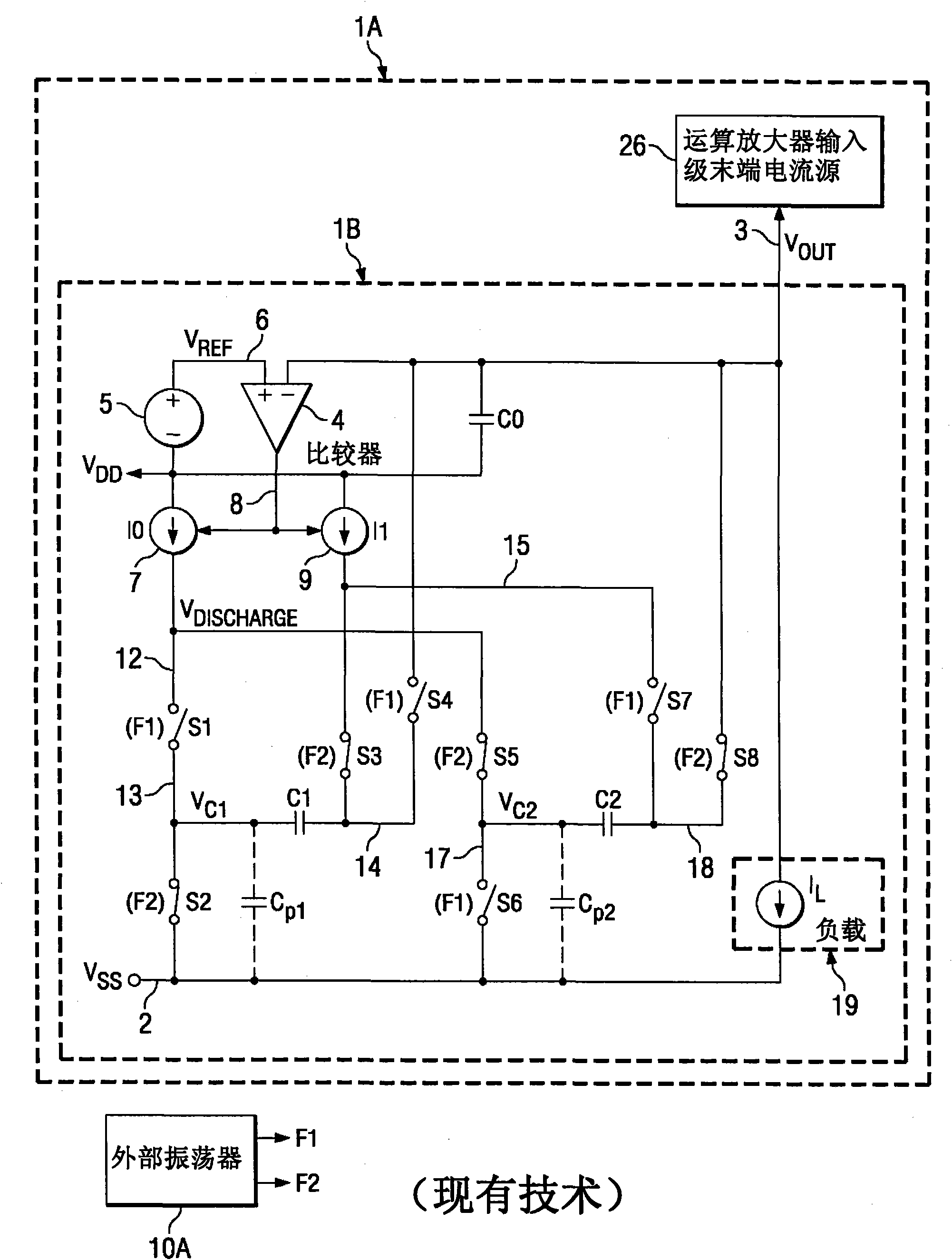
[0026] The present invention provides an energy-efficient way of generating an accurate on-chip low-noise voltage source by providing a differential current-mode charge pump circuit, where the switching of flying capacitors is based on the bottom plate voltage of the flying capacitor currently being discharged (i.e., prior art figure 1 V in DISCHARGE ). The resulting "self-oscillation" ensures the lowest possible flying capacitor switching frequency for any particular load on the charge pump circuit and for any particular supply voltage.

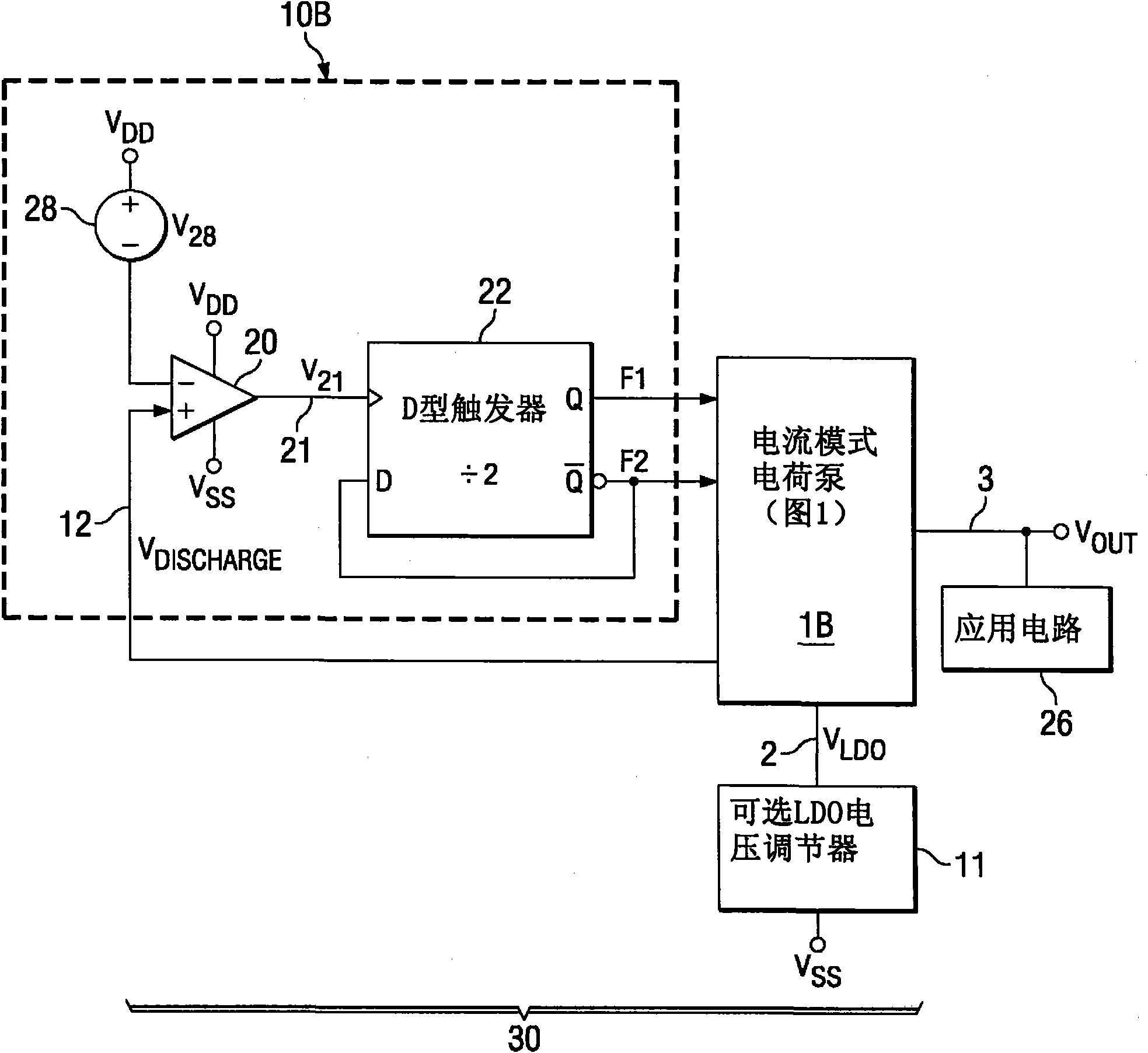
[0027] figure 2 An integrated circuit is shown comprising a self-oscillating charge pump 30 whose output voltage Vout can be applied via conductor 3 to an on-chip application circuit 26, such as a terminal current source of an operational amplifier as described above. The self-oscillating charge pump 30 includes prior art figure 1 In addition to the current mode charge pump 1B and the phase signal generating circuit 10B, the phase signal...


PUM


Abstract

Charge pump circuitry (30) compares bottom plate voltages of first (Cl) and second (C2) flying capacitors in a current mode charge pump (IB) to a reference value (VDD-V28) by means of a comparator (20) which drives a flip-flop (22) that generates first (Fl) and second (F2) complementary phase signals. The first and second phase signals control switching of the flying capacitors to determine a flying capacitor swapping frequency just low enough to prevent saturation of a discharge current source (10) that discharges the flying capacitors into an output conductor (3).

Description

technical field [0001] The present invention relates generally to integrated charge pump circuits, and more particularly to improvements in which power consumption is reduced and the amount of integrated circuit chip area required is reduced. Background technique [0002] The use of an on-chip charge pump in an integrated circuit op amp to bootstrap a current source at the end of its input stage provides an increased rail-to-rail common-mode input voltage range of the op amp. The boosted output voltage produced by the charge pump needs to have low ripple voltage since the ripple voltage creates noise in the terminal current that then propagates to the output of the operational amplifier. It is desirable for the on-chip charge pump to consume as little current and power as possible. [0003] figure 1 A low ripple on-chip current mode charge pump that has been used in the assignee's OPA365 operational amplifier is shown, which is considered to be the closest prior art. exis...

Claims


Application Information

Patent Timeline
Patent Type & Authority Applications(China)
IPC IPC(8): H02M3/07H03L7/093
CPCH02M3/07
Inventor V·V·伊万诺夫T·简吉克
Owner TEXAS INSTR INC
Why Eureka
Try Eureka